Question: (12 points, suggested time 25 minutes)
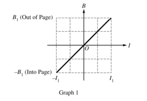
An electromagnet produces a magnetic field that is uniform in a certain region and zero outside that region. The graph above represents the field as a function of the current in the electromagnet, with positive field directed out of the page and negative field directed into the page.
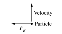
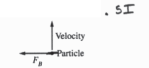
(a) The current in the electromagnet is set at 0.5I1. When a charged particle in the region moves toward the top of the page, the force exerted on it by the field is FB toward the left, as shown above. What changes to the current in the electromagnet could make the magnitude of the force exerted on the particle equal to 2FB and the direction of the force to the right? Support your answer using physics principles.
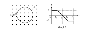
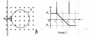
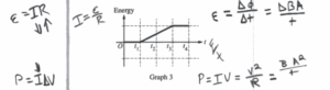
A circuit is made by connecting an ohmic lightbulb of resistance R and a circular loop of area A made of a wire with negligible resistance. The circuit is placed with the plane of the loop perpendicular to the field of the electromagnet, as shown above on the left. The magnetic field changes as a function of time, as shown in Graph 2. The bulb dissipates energy during the interval t1 < t <t3. Graph 3 below shows the cumulative energy dissipated by the bulb (the total energy dissipated since t = 0) as a function of time.

(b) The original bulb is replaced by a new ohmic lightbulb with a greater resistance, but everything else stays the same. How would the cumulative energy graph for the new bulb be different, if at all, from Graph 3 above? Support your answer using physics principles.
(c) The new lightbulb is removed and replaced by the original lightbulb. The magnetic field now changes from 2B1 to −2B1 during the same interval t1 < t <t3. A new cumulative energy graph is created for this situation. How would the new graph be different, if at all, from Graph 3 ? Support your answer using physics principles.
(d) A student derives the following expression for the cumulative energy dissipated by the original bulb during the interval t1 < t <t3 and with the original change in magnetic field shown in Graph 2.
\(Energy = \frac{A^{2}B_{1}R}{4(t_{3}-t_{1})}\)
Whether or not the equation is correct, does the functional dependence of cumulative energy on the elapsed time ( t3−t1) make physical sense? Support your answer using physics principles.
▶️Answer/Explanation
Ans:
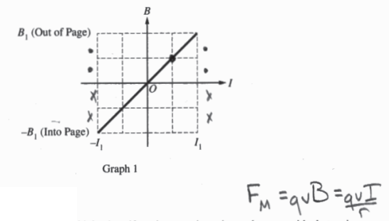
(a) The current could change directions E, be doubled so that it was -I, . Changing direction of the current changes the magnetic field direction as seen by the graph. This would change the direction of F0 to the right by rulers of RAR. Also, by doubling the current, we double the magnitude of the field ξ thereby double the force shown by Fm=qvB.
(b)
The graph would by the same shape, but the slope From t1 to t3 would be less ξ , the final energy dissapated would be less. This is °°° by changing the light’s resistance, we don’t change the V indaced shown by \(E = \frac{\Delta \phi }{t}\) ξ \(E = \frac{\Delta Bcos\theta A}{t}.\) Neither B or A changed. What did change is the current seen by V=IR. R ξ I are inversely prop so I decreases. Energy dissipated is prop to power shown by P=IΔU.If ΔU is constant, but I decreased, then overall energy dissipated must decrease.
(c)
The slope from t1 to t3 would be 4 times greater. °°° the voltage induced is changed shown by \(V = \frac{\Delta \phi }{t}\) ξ \(V=\frac{\Delta Bcos\theta A}{t}.\Delta B\) doubled over the same time period, so V indaced did as well. If n indaced doubled, then so did current seen by V=IR °°° resistance was constant. As stated, the energy dissipated is prop to power seen by \(\frac{\Delta E}{t}\) = P = IΔV. IF ΔV ξ I doubled, then P must quadruple.
(d)
The dependence does make sense °°°it shows that as the time interval increases, the energy dissipated will decrease. This makes sense °°° the magnetic field would be changing at a rate of almost 0, so the change in flux would be almost 0, the indaced emF would be almost 0, ξ thereby the energy dissipated would be almost 0.
Question
A circular loop of wire of resistance 0.2 ohm encloses an area 0.3 square meter and lies flat on a wooden table as shown above. A magnetic field that varies with time t as shown below is perpendicular to the table. A positive value of B represents a field directed up from the surface of the table; a negative value represents a field directed into the tabletop.
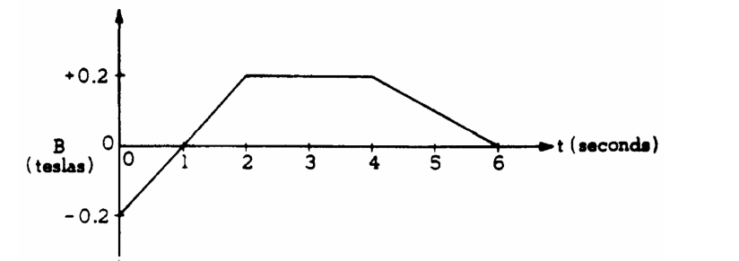
a. Calculate the value of the magnetic flux through the loop at time t = 3 seconds.
b. Calculate the magnitude of the emf induced in the loop during the time interval t = 0 to 2 seconds.
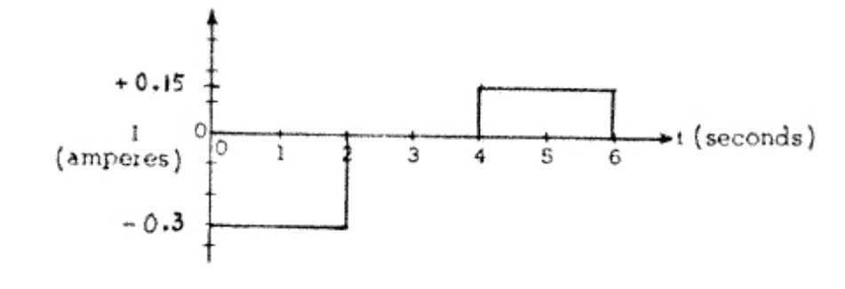
c. On the axes below, graph the current I through the coil as a function of time t, and put appropriate numbers on the vertical scale. Use the convention that positive values of I represent counterclockwise current as viewed from above.
▶️Answer/Explanation
Ans:
a) Ф=BA, read B from the graph at 3 seconds and use the given area (0.2)(0.3) = 0.06 Wb
b) Induced emf = ε=N∆Ф/t … = 1*(BAf – BAi) / t = A(Bf – Bi) / t = (0.3)(0.2 – (–0.2)) / 2 = 0.06 V
c) First, the directions are found based on Lenz Law. From 0–1 the downward flux is decreasing so current flows CW to add back the downward field. Then we hit zero flux at 1 second. Moving 1–2 seconds we want to
maintain the zero flux and we have an increasing upwards flux so the current still flows CW to add downward field to cancel the gaining flux. At 2 seconds the flux becomes constant so current does not flow up until 4 seconds. From 4–6 seconds we are loosing upwards flux so current flows CCW to add back that upwards field.
To determine the current magnitudes. Use V=IR.
From 0–2 sec. 0.06 = I (0.2) I = 0.3 A
From 2–4, I=0.
From 4–6, first determine new emf. Since the slope is half as much as 0–2 sec,
the emf should be half as much as well. Then V=IR … 0.03 = I (0.2) I = 0.15 A
Question
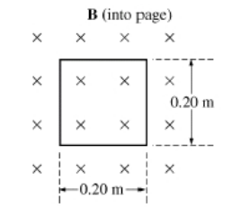
A square loop of wire of side 0.20 m has a total resistance of 0.60 Ω . The loop is positioned in a uniform magnetic field B of 0.030 T. The field is directed into the page, perpendicular to the plane of the loop, as shown above.
(a) Calculate the magnetic flux Φ through the loop.
The field strength now increases uniformly to 0.20 T in 0.50 s.
(b) Calculate the emf ε induced in the loop during this period.
(c) i. Calculate the magnitude I of the current in the loop during this period.
ii. What is the direction of the current in the loop?
_____ Clockwise _____ Counterclockwise
Justify your answer.
(d) Describe a method by which you could induce a current in the loop if the magnetic field remained
▶️Answer/Explanation
Ans:
a) Ф = BA = (0.3)(0.2×0.2) = 1.2×10⁻³ Wb
b) Induced emf … ε=N∆Ф/t … (1)(BAf – BAi) / t … A(Bf – Bi) / t … (0.2×0.2) (0.20–0.03) / 0.5 = 0.014 V
c) i) V=IR … (0.014) = I (0.6) … I = 0.023 A
ii) The magnetic field is increasing into the page. Current will be induced to oppose that change. By the RHR, to create a field out of the page the current must be counterclockwise.
d) If the magnetic field was constant, the area would have to be changed to change the flux and induce the current. To change the area, the loop could be pulled out of the field or it could be rotated in place.