Question
(12 points-suggested time 25 minutes)
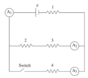
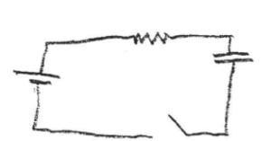
The figure shows a circuit with a battery of emf ε and negligible internal resistance, and four identical resistors of resistance R numbered 1, 2, 3, and 4. There are three ammeters (A1, A2, and A3) that measure the currents I1, I2, and I3, respectively. The circuit also has a switch that begins in the closed position.
(A) A student makes this claim: “The current I3 is twice as large as I2.” Do you agree or disagree with the student’s statement? Support your answer by applying Kirchhoff s loop rule and writing one or more algebraic expressions to support your argument.
(B) Rank the power dissipated into heat by the resistors from highest to lowest, being sure to indicate any that are the same. Justify your ranking.
The switch is opened. A student makes this statement: “The power dissipation of resistors 2 and 3 remains the same because they are in parallel with the switch. The power dissipation of resistor 1 decreases because opening the switch cuts off some of the current going through resistor 1.”
(C) i. Which parts of the student’s statement do you agree? Justify your answer with appropriate physics principles.
ii. Which parts of the student’s statement do you disagree with? Justify your answer utilizing an algebraic argument.
The switch remains open. Resistor 4 is replaced with an uncharged capacitor of capacitance C. The switch is now closed.
(D) i. Determine the current in resistor 1 and the potential difference across the capacitor immediately after the switch is closed.
ii. Determine the current in resistor 1 and the potential difference across the capacitor a long time after the switch is closed.
iii. Calculate the energy CU) stored on the capacitor a long time after the switch is closed.
▶️Answer/Explanation
Ans:
Part (A)
Agree.
1 point-For correctly applying Kirchhoffs loop rule for the upper loop:
ε – I2R – I2R – I1R = 0
ε = 2I2R – I1R
1 point-For correctly applying Kirchhoff’s loop rule to the outer loop:
ε – I3R – I1R = 0
ε = I3R – I1R
1 point-For correctly using the two equations to show that I3 is twice as large as I2:
2I2R – I1R = I3R – I1R
2I2R = I3R
2I2 = I3
Part (B)
No points are awarded for the correct ranking of: P1 > P4 > P2 = P3.
1 point-For indicating that Power= I2R and that all the resistors are the same. Therefore, the ranking is based on the current passing through the resistors.
1 point-For indicating that resistor 1 receives the most current as all the current must pass through it AND that resistor 4 receives more current than resistors 2 and 3 AND that resistors 2 and 3 receive the same current because they are in the same conductive pathway.
Part (C)
(i.) Agree that the power will go down for resistor 1.
1 point-For indicating that when the switch is opened, there is only one path left for the current to pass through. This means the total resistance of the circuit increases. The potential difference across resistor 1 will decrease, which will bring its power dissipation down as well.
(ii.) Disagree that resistors 2 and 3 are unaffected.
1 point-For deriving a correct expression for the original current passing through resistors 2 and 3:
1 point-For deriving a correct expression for the new current passing through resistors 2 and 3:
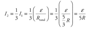
\(I_{2}=I_{1}=\frac{\varepsilon }{R_{total}}=\frac{\varepsilon }{3R}\)
The new current is larger than the old; therefore, the power dissipation goes up. (Note that this argument can be also be made using potential difference and would also receive credit.)
Part (D)
(i.) Immediately after the switch is closed, the capacitor acts like a short-circuit wire that allows the current to bypass resistors 2 and 3.
1 point-For indicating that the current through resistor 1 will be \(I_{1}=\frac{\varepsilon }{R},\) and that the potential difference across the capacitor is zero (ΔVC =0).
(ii.) After a long period of time, the capacitor becomes fully charged and acts like an open switch in the circuit.
1 point-For indicating the current through resistor 1 will be: \(I_{1}=\frac{\varepsilon }{3R}.\)
1 point-For indicating that the potential difference across the capacitor will be equal to that of resistors 2 and 3 combined, because the capacitor is in parallel with them: \(\Delta V_{C}=\frac{2}{3}\varepsilon .\) Note this can be stated in words or symbolically to receive credit.
(iii.)
1 point-For calculating the potential energy stored by the capacitor: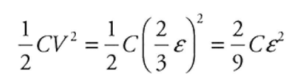
Question
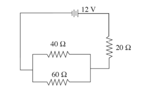
The circuit shown is built and the voltage source supplies voltage for 15 minutes before the battery is completely drained. Assume the voltage supplied by the battery is constant at 12 V until the battery is drained, after which the battery supplies o V.
(a) What is the equivalent resistance of the circuit?
(b) Two students are discussing the apparatus. Student 1 says, “If the 20 n resistor were not present, the overall resistance of the circuit would have been lower and the battery would have lasted longer.” Student 2 says, “If the 20 n resistor were not present, I think the power output would have been higher and the battery would have drained faster.”
(i) Use equations to show whether the overall resistance would have been lower without the 20Ω resistor present.
(ii) Use equations to determine whether the overall power output would have been higher.
(iii) Which student is correct about the battery life?
(c) The 20 Ω resistor is replaced with a capacitor.
(i) As soon as the circuit is connected, explain without using equations how the current drawn out of the battery compares between the original circuit and the circuit with
the capacitor.
(ii) After the capacitor has been connected for a long time, but before the battery is completely drained, how does the current drawn out of the battery compare between the
original circuit and the circuit with the capacitor?
▶️Answer/Explanation
Ans:
(a) The resistors in parallel are combined first.
Req-1 = 40-1 + 60 -1
Req = 40
The total equivalent resistance is then Rtotal = 24 + 20 = 44 Ω.
(b) (i) Without the resistor, there would only be the parallel resistor combination.
R-1 total = 40-1 + 60 -1
R total = 40 Ω.
(ii) P =IV= \(\left ( \frac{V}{R} \right )V,\) so a higher resistance results in a lower power output for the same battecy.
(iii) A lower power output means that it will take more time for the energy to be used up, so student 1 is correct.
(c) (i) As soon as the circuit is connected with the capacitor, the capacitor acts as if it had no resistance. This is exactly like
(b, i). The lower resistance would cause a greater current to be drawn from the battecy.
(ii) After the capacitor is fully charged, no more current can flow in the branch of the circuit with the capacitor. The capacitor is in series with the battecy, so there will be no
current drawn from the battecy.
Question: (10 points, suggested time 20 minutes)
Some students are investigating the behavior of a circuit with four components in series: a resistor of resistance R, a capacitor of capacitance C, a battery with potential difference ε , and a switch. Initially, the capacitor is uncharged and the switch is open.
(a)
i. Determine the current in the resistor and the potential difference across the capacitor immediately after the switch is closed.
ii. Determine the current in the resistor and the potential difference across the capacitor a long time after the switch is closed.
(b) The switch is opened, the capacitor is discharged, and a second, identical capacitor is added to the circuit in series with the other components. The switch is then closed again.
i. A long time after the switch is closed, the energy stored in the single capacitor in the original circuit is U1 , and the total energy stored in the two capacitors in the new circuit is U2 . Calculate the ratio U1 /U2 .
ii. The two capacitors in series are to be replaced with a single capacitor that will have the same energy U2 . Indicate a plate area and a distance between the plates for the new capacitor, compared with one of the original capacitors, that will accomplish this. Support your reasoning using appropriate physics principles and/or mathematical models. The students are then asked to design two circuits each containing a switch, a battery with a small internal resistance, a lightbulb, and a capacitor. In arrangement 1, the bulb should gradually light up after the switch is closed, becoming brightest after the switch has been closed a long time. In arrangement 2, the bulb should be brightest when the switch is first closed, getting dimmer with time, and going out completely when the switch has been closed for a long time.
(c) Using standard symbols, draw two circuit diagrams, one showing a possible circuit for arrangement 1 and the other showing a possible circuit for arrangement 2. Justify your circuit diagrams with a paragraph-length explanation referring to the properties of lightbulbs and capacitors in circuits and the conservation of energy and/or the conservation of charge.
▶️Answer/Explanation
Ans:
i.
As across capacitor, potential difference = 0 volts current in resistor = \(\frac{\varepsilon E}{R}\) amps
ii.
Current in resistor = 0 amps Potential difference across capacitor = ε Volts
(b) i.
\(U_{1} : \frac{1}{2}C (\Delta )^{2}=\frac{1}{2}\varepsilon ^{2}\) \(\rightarrow \frac{U_{1}}{U_{2}}=\frac{\frac{1}{2}\varepsilon ^{2}}{\frac{1}{4}\varepsilon ^{2}}=2\varepsilon ^{2}\)
\(U_{2} = \frac{1}{2}V \left ( \frac{\varepsilon }{2} \right )^{2}+\frac{1}{2}V \left ( \frac{\varepsilon }{2} \right )^{2}=\frac{1}{8}V\varepsilon ^{2}+\frac{1}{8}C\varepsilon ^{2}=\frac{1}{4}C\varepsilon ^{2}\)
ii.
\(U_{2} initial= \frac{1}{4}C\varepsilon ^{2}\)
\(U = \frac{1}{2}C\Delta V^{2}\)
new ΔV = ε, so new capacitance must be \(\frac{C}{2}\) to have \(C_{2new}=\frac{1}{4}C\varepsilon ^{2}\)
To half capacitance, one can either have the area per plate or double the distance between them, b/c \(C = \frac{\varepsilon _{0}A}{d}.\)
(c)
Arrangement 1 =
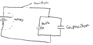
In this arrangement, immediately once the switch is closed the capacitor is closed the capacitor acts like a stretch of open wire. Thus, by the junction rule, when current flows into the parallel system in the circuit, the last majority of it will flow into the branch w, less resistance (the capacitor, so the bulb will be very dim, b/c brightness is proportional to power, which = IV. After a while, the capacitor will develop a higher and higher resistance as it fills up charge & its stopping potential increases. As the resistance in the capacitor increases, more current goes through the bulb in older to conceive charge, so b/c P=IV, its brightness. Eventually, when the capacitor is completely charged, the bulb will get all of the circuits current & thus be @ its brightness.
Arrangement 2 =
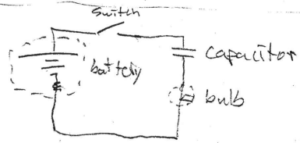
Initially, the capacitor acts like an open wire. Thus b/c power = I2R and power is proportional to brightness, the bulb will be brightest @ this time, b/c \(I = \frac{V}{R_{total}}\) & Rtotal will be at a minimum. As the capacitor fills w/ charges its resistance increases, so the current going through the bulb decreases and the bulbs brightness decreases. Eventually, the capacitor fills, and develops a stopping potential equal to the battery’s voltages w/charge so no current flows through the bulb, and thus the bulb goes out.