Focus Question: How do magnetic fields form near conductors?
- When a current-carrying conductor lies in a magnetic field, the field exerts magnetic forces on the moving charges in the conductor. The forces are transmitted to the conductor and the conductor experiences a force along its length.
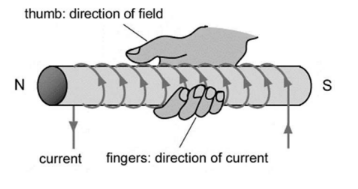
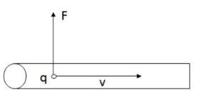
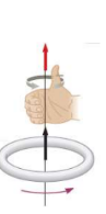
- Direction of force: Given by right hand rule. Thumbs points in the direction of current, fingers curl in the direction of the magnetic field.
- Magnitude of force:
A current carrying wire has many charged particles, each with a magnetic
force on them.
$
F=B q v
$
The charge is the total charge of all the electrons:
Total charge $q=$ elementary charge electron density $x$ number of electrons
$\rightarrow q=$ elementary charge electron density $*$ volume of wire $=e(n A L)$
where $\mathrm{A}=$ cross section of the wire and $\mathrm{L}=$ length of the wire
$
F=B(e n A L) v \rightarrow F=B(\text { naVe }) L
$
$
\begin{gathered}
F=B I L \\
F=I \vec{L} x \vec{B} \\
F=B I L \sin \theta
\end{gathered}
$
Apply BIl .
Example A: A wire that is $8 \mathrm{~m}$ long carries a $5 \mathrm{~A}$ current from left to right in the plane of this page. A 1.5 T magnitude field points up and to the right in the plane of this page at a $60^{\circ}$ as shown. What is the magnitude and direction of the force on the wire?
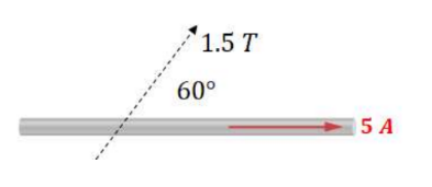
Answer/Explanation
$
F=B I L \sin \theta=(1.5 T)(5 A)(8 m) \sin 60^{\circ}=52 N
$
By the right hand rule, the force is out of the page.
Example C: A pair of long parallel wires are separated by a small distance, r. If the two currents shown are established in the wires, what is the force per unit length they exert on each other?
Answer/Explanation
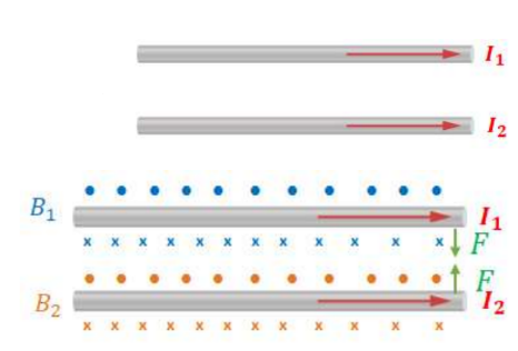
By the right hand rule, both wires have a field that is out of the page above them and into the page below them. Consider the magnetic force on wire 1 due to wire 2. Wire 1 is above wire 2 so the field due to wire is out of the page. Positive charge in wire 1 moves to the right, so by the right hand rule, the force is down.
For wire 2, it experiences field into the page due to wire 1 and have positive charge moving to the right, so the force on wire 2 is up by the right hand-rule, meaning the wires attract each other.
The magnitude of the force on wire 1 is: $F=B_2 I_1 L \rightarrow \frac{F}{L}=\left(\frac{\mu I_2}{2 \pi r}\right) I_1$
$
\rightarrow \frac{F}{L}=\frac{\mu I_1 I_2}{2 \pi r}
$
- Wires in the same direction attract each other. * “If they flow together, they go together”.
- Wires flowing in opposite directions repel each other.
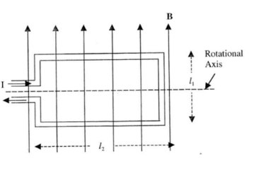
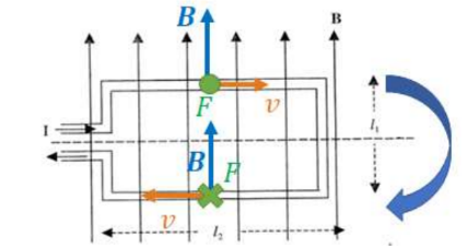
Torque on a Current Loop.
- A magnetic couple is a pair of equal but opposite forces that are anti- parallel separated from each other.
- Torque due to a couple:
$
\begin{gathered}
\tau=(\text { force }) x(\text { distance between lines of action }) \\
\tau=F b \sin \alpha=B I a \sin \alpha \\
\tau=B I A \sin \alpha
\end{gathered}
$
*For multiple loops: $\tau=n B I A \sin \alpha$
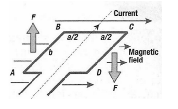
Example E: A rectangular loop of wire that carries current I is placed in a uniform magnetic field B as shown. What torque does it experience?
Answer/Explanation
The current goes in opposite direction above and below the center line as shown, causing opposing forces, allowing the loop to rotate as shown since both torques are in the same direction.
$
\begin{gathered}
\sum \tau=\tau_{\text {on top wire }}+\tau_{\text {on bottom wire }}=\left(B I l_2\right)\left(\frac{l_1}{2}\right)+\left(B I l_2\right)\left(\frac{l_1}{2}\right) \\
\rightarrow \tau=B I l_1 l_2
\end{gathered}
$
This is consistent with $\tau=$ BIA since $l_1 l_2$ is the area of the loop.
Example $\mathbf{F}$ : A square coil with 12 turns lies in the xy plane. Each side has a length of $\mathrm{s}=4.0 \mathrm{~cm}$ and the sides are parallel to the coordinate axes. A uniform magnetic field points in the y-direction, $B=(2 \hat{\jmath}) T$. Calculate the current needed to produce a net torque about the $\mathrm{x}$-axis of $1.92 \times 10^{-3} \mathrm{Nm}$.
$
\tau=n B I A \rightarrow I=\frac{\tau}{n B A}=\frac{.00192 \mathrm{Nm}}{12(2 \mathrm{~T})(.04 \mathrm{~m})^2}=.05 \mathrm{~A}
$
- Torque on a loop of current:
$A$ – area vector of loop
$\mu$-magnetic moment, describes how loop reacts to torque
$
\begin{aligned}
\mu & =I \vec{A} \\
\tau & =\mu x B
\end{aligned}
$