EXPLANATIONS
Objective Questions
8. (d) Resistance between terminals A and B
C
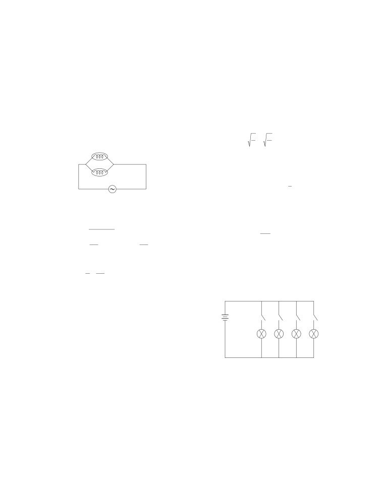
1. (c) Option (c) represents correct set-up for studying the
dependence of the current on the potential difference across
a resistor because ammeter A is connected in series while
voltmeter V is connected across parallel of resistor R.
2Ω
2Ω
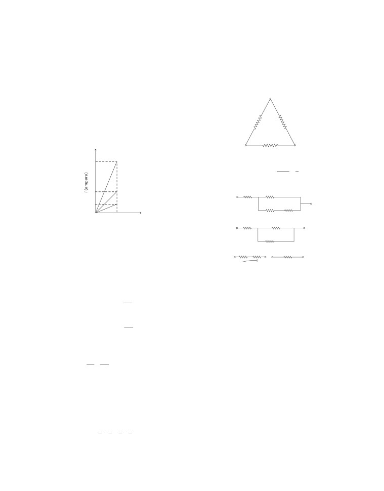
2. (c) At given voltage, current I is inversely proportional to
resistance, i.e. I
∝
1. At given voltageIis maximum forR1,
R
therefore, R1 is minimum.
A
2Ω
B
I
= (2 Ω, 2 Ω in series) parallel to 2 Ω
1
4
×
2
4
=
(2
+
2)||2
Ω
=
4
Ω||
2
Ω=
=
Ω
6
3
9. (a) As, Req
I2
3!
3!
X
Y
I3
3!
3!
V(volt)
3!
3!
At given voltage,
1
I >I
2
>
I
3
∴
R <R <R
⇒
1
2
3
or
3
R >R >R
2
1
6!
3. (c) Resistivity depends on the nature of material and the
3!
2!
⇒
⇒
temperature but does not depend on the shape of the
5!
3×6
resistor.
3+6=2!
4. (a) True; Specific resistance of a conductor increases on
10. (b) The filament of electric bulb is made up of tungsten
increasing its temperature.
because it has a very high resistance.
5. (c) In first case,
11. (c), As heat produced, H = I2Rt
RAʹ
Resistivity of the conductor, ρ =
…(i)
Here, R =2 Ω
l
2
For AD, H1
=3
× 2 ×1 =18J
In second case,
2
RAʹ
For DG, H
=
(−2)
×2 ×1=8J
Resistivity of the conductor, ρ =
…(ii)
2
2
l
2
For GJ, H
3
=
(1)
×2 ×1=2J
Q For same material, resistivity of the conductor will be
same.
∴ Total amount of heat produced in 3 s is,
H=H +H +H
So, on substituting the value of ρ in Eq. (ii), we have
1
2
3
RA RAʹ
=
⇒ ʹ=2A
⇒
H =18 + 8 + 2 = 28J
l
2l
12. (b) Electric power determines the rate at which energy is
6. (b) A material that offers higher resistance as compared to
delivered by a current.
conductors to the flow of electron, so has small number of
free electrons is called a poor conductor.
13. (c) Bulbs are rated presuming that they all are connected
with the same voltage supply. In parallel combination,
7. (a) The maximum resistance is obtained when resistors are
voltage across each bulb is same, so greater the watt, greater
connected in series combination.
the brightness.
Thus equivalent resistance
∴ Brightness (B) of 3 bulbs are as follows
Req =R +R +R +R
1
2
3
4
B >B >B
100
60
40
1
1
1
1
=
+
+
+
=2 Ω
2
2
2
2
⇒
C
B >B >B
B
A
14. (d) Given, power, P =1 kW =1000 W
22. (i)
(c) The SI unit of electric energy per unit time is watt.
electric energy
J
−
Voltage,
V = 220 V
Q
P=
=
=
Js
1 =W
time
s
Current,
I= ?
1000
(ii)
(b) 1 kilowatt-hour is equal to 3.6
×106
joule.
I= P
=
=
4.5A
V
220
(iii)
(a) AsE ∝ t
Thus,the rating offuse-wire is5A whichisgreater than4.5A.
∴ When the time of operating the heater is doubled, the
−3
energy dissipated is doubled.
15. (a) Given, V =
V, I =100
mA
=100
×10
A
=
01
. A
(iv)
(c) Given, P = 60 W, t =1 min =1 × 60 s
∴ Power, P = VI =
∴
E =P × t = 60 × 60
⇒ P = 75mW
⇒
E = 3600 J
16. (c) As we know, resistance of conductor depends on the
(v)
(d) Given, I = 5A, R = 2 Ω, t = 30 min =1800 s
length of conductor as R ∝ l
2
∴
= 5 × 5 × 2 ×1800
As the length of wire is more, resistance of conductor is
⇒ E = 90000 = 90kJ
more.
∴A is true but R is false.
Subjective Questions
1. Ohm’s law gives the relationship between current I flowing
17. (a) Copper conducts the current without offering much
in a metallic wire and potential difference V, across its
resistance due to high electrical conductivity. Hence,
terminals. According to this law, the electric current flowing
conducting wires are made of copper.
through a conductor is directly proportional to the potential
∴BothA and Rare true and Risthe correct explanationofA.
difference applied across its ends, providing physical
18. (b) Resistors are connected in series, when they join
conditions remains unchanged.
end-to-end consecutively with each other. In parallel
i.e.
V ∝ Ior V = IR
combination, the total resistance is always less than the least
where R is constant of proportionality called resistance of
resistance in combination.
conductor at a given temperature.
∴ Both A and R are true but R is not the correct explanation
of A.
Unit of resistance is ohm. It is said to be 1 ohm, if potential
difference of 1 volt across the ends of the conductor makes a
19. (b) Fuse is a safety device that is used in household circuits.
current of 1 A to flow through it.
It is connected in series with the main supply.
1V
−1
Fuse consists of an alloy of lead and tin which has
i.e.
1 ohm (Ω) =
=
VA
1A
appropriate melting point.
2. Resistance is the property of a conductor by virtue of which
∴ Both A and R are true but R is not the correct explanation
it opposes/resists the flow of charges/flow of current through
of A.
it. Its SI unit is ohm and is represented by the Greek letter
2
V
V
Ω (ohm). Resistance of a conductor is given by R
=
20. (a) The resistance, R
=
I
P
1
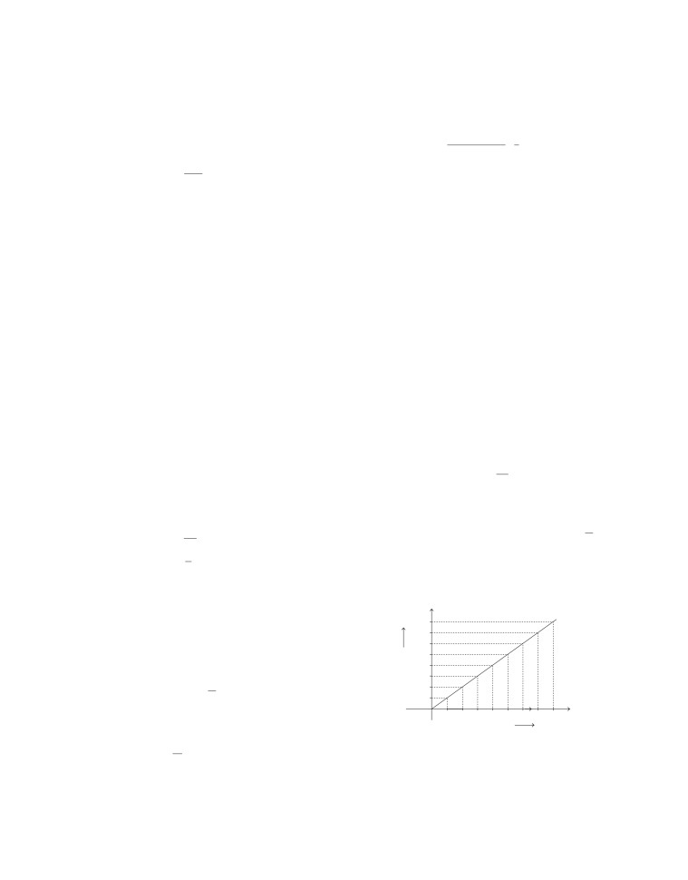
3. Scale : At x-axis, 1 div (1 cm) = 0.1 A
R∝
P
At y-axis, 1 div (1 cm) = 0.5 V
i.e. Higher the wattage of a bulb, lesser is the resistance and
The graph between current and potential difference is
so it will glow brighter.
shown below.
∴Both A and R are true and R is the correct explanation of A.
Y
5.0
21. (i)
(a) Materials that follow Ohm’s law are called ohmic
4.0
conductor. V - I graph is a straight line passing from
3.0
origin for ohmic conductors.
V
2.5
(ii)
(c) V - I curve for insulator is straight line that lies on
(Volts)
2.0
voltage axis at room temperature.
1.5
I
1.0
(iii)
(b) Slope of V -I graph =
=1.
V R
0.5
(iv)
(d) On increasing the voltage, the resistance remains
X
0.1
0.2
0.3
0.4
0.5
0.6
0.7
0.8
same but current increases.
I (Ampere)
(v)
(a) Given, V = 9V, I = 0.1 A
9
Resistance (R) of the resistor is determined by the slope of
∴
R = V
=
=
90
Ω
V-I graph.
I
01
V
2
⎡0.25
⎤
∴ Resistance = R=Slope of graph =
−3
5×
π
×
×10
I
⎢
⎥
RA
⎣
2
⎦
−
y
1.5−1.0
⇒
l
=
=
2
1
−8
∴
R= y
=
ρ
0.8×10
2
x −x
1
0.3−0.2
D
0.5
[Q A = πr2 and r
=
]
=
=
5
Ω
2
0.1
−8
5×
π
×1.56×10
=
=
3
m
4. Alloys have a higher resistivity than their constituent metals.
−8
0.8×10
They do not oxidise or burn at higher temperatures as they
ρl
have high melting point. Thus, they are used to make coils of
(ii)
∴Resistance, R =
electrical toasters and electric irons rather than pure metals.
A
ρl
ρl
4
5. (i) Following factors on which resistance of a wire depends
=
×
2 =
⎛D⎞
π D2
(a) length of wire : R∝l
π
⎜
⎟
⎝
2⎠
(b) area of cross-section of wire : R∝1
D
[Q A = πr2 and r
=
]
A
2
(c) resistivity of material of wire : R∝ ρ
ρl
R'= ρl=
[Q D has become 2D]
2
∴
R=ρ l
A
⎛ 2D⎞
A
π
⎜
⎟
⎝
2
⎠
(ii) Metals are good conductors as their resistivity is very low
l
whereas glass is a bad conductor having high resistivity.
= ρ
πD2
(iii) Alloys are used as heating elements as their resistivity
and melting points both are very high.
R'
ρl
ρl×4
Now,
=
÷
2
6. The given circuit is shown below
R
πD2
πD
2
I
ρl
πD
1
=
×
=
A
2
πD
ρl
×
4
4
∴
R'=R
4
12 V
R1=4 Ω
R2
Thus, resistance will decrease by 4 times.
8.
6V
+
-
-
B
A
K
Let R be the resistance of the entire circuit.
+
5Ω
8Ω
12 Ω
Given, overall current needed, I = 9 A
R1
R2
-
Voltage,
V =12 V
+
V
Using Ohm's law, V = IR
12
4
Equivalent resistance of the circuit,
⇒
R = V
=
=
Ω
I
9
3
1
R=R +R +R
2
3
=5 + 8 + 12 = 25Ω
Now, the resistors R1 and R2 are in parallel combination.
[QR , R
1
2 andR3 areconnectedinseries]
1
1
1
1
1
1
In series combination, current flowing through all the
∴
=
+
⇒
=
+
R R
R
R
4
R
resistances is same and equal to the total current flowing
1
2
2
through the circuit.
3
1
1
4
⇒
=
+
[QR =
Ω]
∴ Current in the resistors,
4
4
R
2
3
6
1
3
1
2
1
I= V
=
=
0.24 A
⇒
=
−
=
=
R
25
R
4
4
4
2
2
∴ Ammeter reading = 0.24 A
⇒ R2
=
2
Ω
Potential across 12 Ω resistance,
So, the student should choose 2 Ω resistor.
V =IR = 0.24 ×12 = 2.88V
7. Given, diameter = 0.25 mm
∴ Voltmeter reading is 2.88 V.
−8
Resistivity, ρ =
0.8×10
Ω-m
9. Parallel combination of resistances is highly useful in
(i) Resistance, R = 5 Ω
circuits used in daily life, as the circuits used have
ρl
We know that, R =
components of different resistances requiring different
A
amounts of current.
This type of combination in a circuit divides the current
Now, the given circuit can be redrawn as shown below
among the components (electrical gadgets), so that they can
R5=3 Ω
+
-
have necessary amount of current to operate properly. This
is the reason of connecting electrical appliances in parallel
combination in household circuit.
A
R''=2 Ω
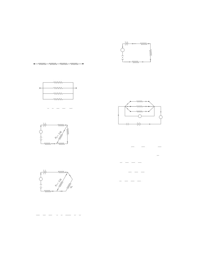
10. (i) Resistance is maximum when resistors are connected in
series.
K
4Ω
8Ω
12 Ω
24 Ω
A
B
R1=3 Ω
Rmax = 4 + 8 +12 + 24 = 48 Ω
Now, it is clear from the above circuit that all the resistances
R5,Rʹʹ and R1 are in series combination.
(ii) Resistance is minimum when resistors are connected in
parallel.
As, current through R1,Rʹʹ and R5
is same.
4Ω
∴ Equivalent resistance of the circuit is
R = R + Rʹʹ+R
3 Ω+2 Ω+3 Ω=8 Ω
A
B
5
1 =
8Ω
12. The following figure shows the connection of resistors in
parallel
12 Ω
R1
24 Ω
I1
R2
⎡1
1
1
1
⎤
24
1/
+
+
+
=
Ω=
2
Ω
I2
R3
Rmin. =
⎢
⎥
⎣4
8
12
24⎦
12
I3
I
+
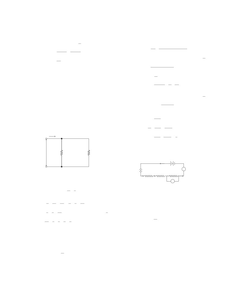
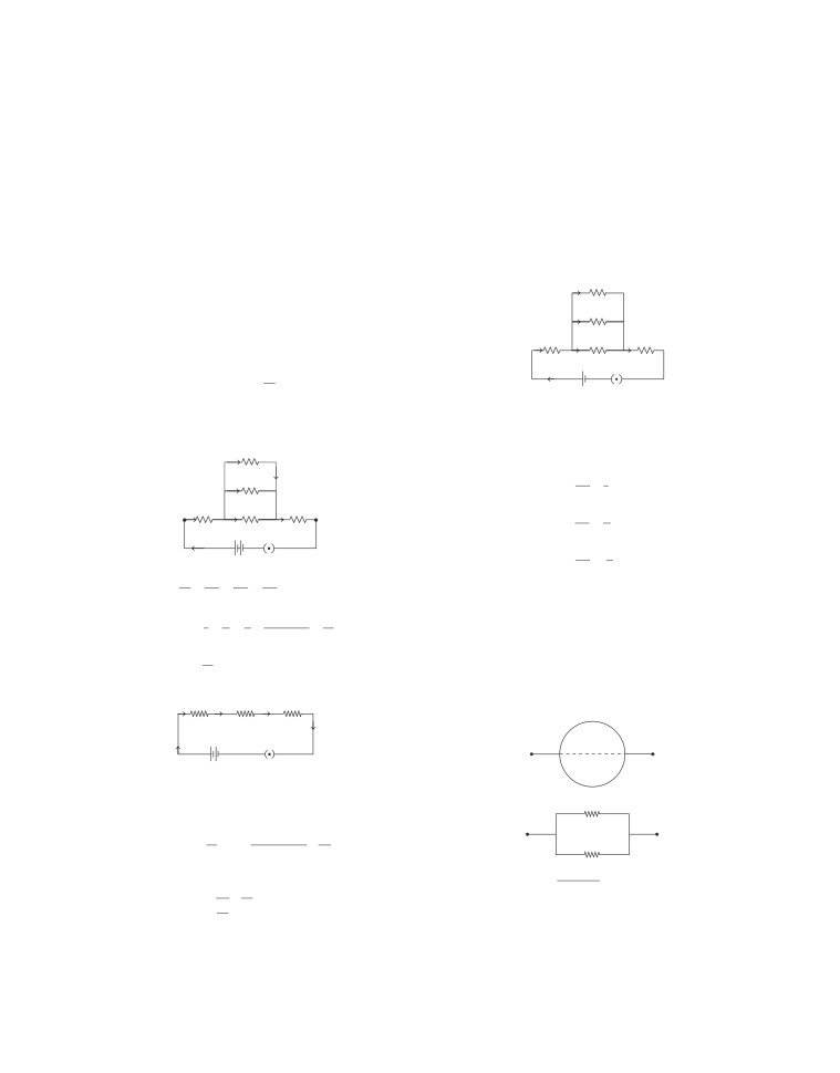
11. From the combination, it can be observed that R2 and R3 are
I
V
+
-
A
in series order.
-
R5
=3Ω
+
-
+
-
K
V
A
R3=3Ω
An applied potential difference V produces current I1 in
1
R ,I
2
in R2 and I3 in R3.
K
Total current, I = I
1
+I
2
+I
3
…(i)
V
V
V
R1=3Ω
R2=3Ω
By Ohm’s law, I
1
=
,I
2
=
and I
3
=
R
1
R
2
R
3
As current through R2 and R3 is same. So, their equivalent
V
If R is the equivalent resistance, then I
=
resistance is Rʹ=R
2
+R
3=
3Ω+3Ω=6Ω
R
V
V
V
V
Now, the given circuit can be redrawn as shown below
Thus,
=
+
+
[from Eq. (i)]
R
R
1
R
2
R
3
R5=3Ω
+
-
⎛
1
1
1
⎞
⇒ V
=
V⎜
+
+
⎟
R
⎝
1
R R R
2
3
⎠
A
1
1
1
1
⇒
=
+
+
R R
1
R
2
R
3
K
=6Ω
13. The brightness of glow of bulb P will increase and brightness
of glow of bulb Qwill decrease.
R1=3Ω
This is because, on closing S, bulbs Q and R will be in parallel
Now, it can be seen that R4 and Rʹ are in parallel
and the combination will be in series with bulb P. Hence, the
combination. As, currents through R4 and Rʹ are
total resistance of the circuit will decrease and the current
different. So, their equivalent resistance can be calculated
flowing in the circuit will increase. Therefore, the glow of
as below
bulb P will increase.
1
1
1
1
1
1+
2
3
1
Also, bulbs Qand R will be in parallel in this case. So, the
=
+
=
+
=
=
=
Rʹʹ Rʹ R
4
6
3
6
6
2
current gets divided and lesser current flows through Qand
hence the glow of bulb Qdecreases.
∴ Rʹʹ = 2 Ω
14. (i) According to Joule’s law of heating, amount of heat
P = V2/R is used when potential difference(V)across every
produced in a resistor is
component of the circuit is constant. This expression is used
(a) directly proportional to square of current flowing
in case of parallel combination in the circuit. In series
through the resistor.
combination, R is greater than the value of R in parallel
combination.
∴
H∝I2
(b) directly proportional to resistance of the resistor.
20. Resistance, R = 2 Ω
∴
H∝R
Maximum power, Pmax =18 W
(c) directly proportional to time for which the current
Maximum current, Imax
=
?
flows through the resistor.
P=I2R
∴
H∝t
P
18
⇒
I
=
=
=
3A=Imax
Hence,
H=I2Rt
R
2
(ii)
Maximum current that can flow through 2 Ω resistor is 3 A.
L1
100 W, 220 V
This current divides along B and C because they are in
parallel combination. Voltage across B and C remains same
L2
60 W, 220 V
and hence I
∝
1. Since, B and C have same resistance 2 Ω
R
3
each, and has same current. i.e. I =
=1.5 A flowing through
2
220 V
B and C.
21. Given, power, P =1500 W,
Here, potential, V = 220 V
Power, P1 = 100 W, P2 = 60 W
Voltage, V = 250 V
As, current drawn is given by
(i) Electric current drawn,
P)
I= Power(
[From P = VI]
1500
Voltage (V)
I= P
=
=
6A
V
250
100
60
So,
I1
=
=
A and I =
2
=
A
(ii) Energy consumed, E = Power × Time
220
220
=1500 × 50
[Q t = 50 h]
15. Given, R1
=
2
Ω, R2
=
4
Ω, t = 5s , V = 6 V
= 75000 Wh = 75 kWh
∴Net resistance, R = R
1
+R
2=
2 Ω+ 4 Ω=6 Ω
V
6V
[Q 1 kW = 1000 W]
∴ Current, I
=
=
=1A
R
6
Ω
= 75 unit
[Q 1 unit = 1 kWh]
In series, same 1 A current passes through both resistors.
(iii)Q Cost of energy consumed = 75 × 6 = ` 450
2
∴ Heat dissipated, H = I2R
1
×t
=(1)
×
4
×
5= 20 J
22. The given circuit is shown below
16. The heating element of heater is made up of an alloy that has
very high resistance. So when the current flows through it, it
becomes very hot and glows red. But the resistance of cord
60 V
is less because it is made up of copper or aluminium, so it
does not glow.
3A
A
4A B
5A C
3A D
17. Electric fuse is used to protect the electrical circuit from
overloading and short circuit. When the current flowing
through a circuit exceeds the safe limit, the temperature of
fuse wire increases and due to heating effect, it gets melt
and breaks the circuit.
(i) In the circuit, all the lamps have same voltage, i.e. 60 V
18. The SI unit of electric power is watt (W). It is the power
but each lamp is having different current. So, the lamps
consumed by a device that carries 1 A of current when
are arranged in parallel combination.
operated at a potential difference of 1 V. Thus,
(ii) The two advantages of lamps in parallel combination are
1W =1 volt ×1 ampere =1 VA
(a) if one lamp gets faulty, it will not affect the working
The commercial unit of electrical energy is kilowatt hour
of other lamps.
(kWh), commonly known as ‘unit’.
(b) in parallel combination of lamps, each lamp will use
1 kWh =
J
the full potential of the battery.
19. P = I2R is used when current flowing in every component of
(iii) The lamp with the highest power will glow the brightest.
the circuit is constant. This is the case of series combination
As, power = Voltage × Current
of the devices in the circuit.
In this case, all the lamps have same voltage i.e., 60 V.
For lamp A , current = 3 A
Potential drop at R1 ,
∴
Power = 60 × 3 = 180 W
1
V =IR
1
1
=2 ×2 =4V
For lamp B, current = 4 A
Potential drop at R5 ,
∴
Power = 60 × 4 = 240 W
V =IR
=2 ×2 =4V
5
5
5
For lamp C, current = 5 A
Now, potential drop at Rʹ , Vʹ can be calculated as
∴
Power = 60 × 5 = 300 W
1
V = V + V + Vʹ
5
For lamp D, current = 3 A
⇒
9 = 4 + 4 + Vʹ
∴
Power = 60 × 3 = 180 W
⇒
Vʹ = 1 V
As, the lamp C is having the maximum power, so it will
I2
R2
glow the brightest.
(iv) Let R be the total resistance of the circuit.
I3
Total current in the circuit, I = 3 + 4 + 5 + 3 = 15 A
R3
I
I
5=
I=I1
R1
Voltage, V = 60 V
Using Ohm's law, V = IR
I4
R4
R5
60
⇒
R = V
=
=
4Ω
+
-
I
15
I
K
23. In the given circuit, R ,R
2
3
and R4 are in parallel
As R ,R
and R4 are in parallel combination, so potential
2
3
combination. As, currents through R ,R
2
3
and R4 are
drop at all resistances will be same as 1 V.
different. So, their equivalent resistance R is
V =V =V =V
2
3
4
ʹ=
1V
1Ω
Current through R2 ,
R2
V
2
Vʹ
1
2Ω
I
=
=
=
=1A
2
R
2
R
2
1
R
3
2Ω
3Ω
2Ω
V
Vʹ
1
A
B
3
Similarly,
I
3
=
=
=
=
05A
R
1
R4
R5
R
R
2
3
3
+
–
V
Vʹ
1
4
K
and
I
=
=
=
=
033
A
9V
4
R
4
R
4
3
1
1
1
1
=
+
+
24. (i) A states that the electric current flowing through a
Rʹ
R
2
R
3
R
4
conductor directly proportional to the potential
difference applied across its ends provided the physical
1
1
1
6
+
3
+
2
11
=
+
+
=
=
conditions such as temperature remains unchanged.
1
2
3
6
6
(ii) An ammeter is connected in series in a circuit.
6
⇒
Rʹ =
Ω
(iii) Given, P =100 W and time t =1 min = 60 s.
11
As, energy E = Pt =100 × 60 = 6000 J
Now, the given circuit can be redrawn as shown below
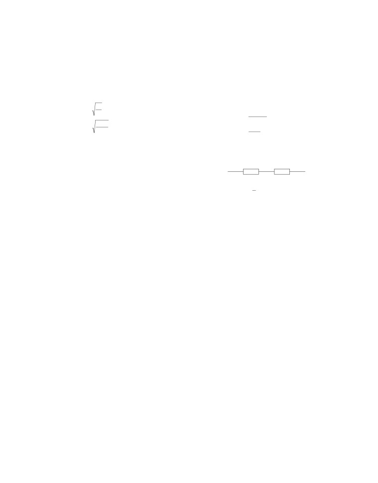
(iv) Given, a wire with resistance 5 Ω.
2Ω
6/11 Ω
2Ω
A
B
Now, wire is converted into a ring as shown below
R1
Rʹ
R5
9V
K
A
B
+
-
Now, R1,Rʹ and R5 are in series combination. As, current
through R ,Rʹ and
R
is same.
1
5
The equivalent circuit,
So, equivalent resistance of the whole circuit is
1
R = R + Rʹ + R
5
A
B
6
22+
6+
22
50
=2+
+
2 =
=
Ω
11
11
11
Now, total current flowing through the circuit,
2.5×
2.5
Hence, R =R
=
=
1.25W
eq
AB
9
99
2.5+
2.5
I= V
=
=
≈
2A
R
50
50
25. Given, resistance of lamp (R )
1
= 20 Ω
11
Resistance of conductor (R )
2
=
4
Ω
Current through R1 and R5 will be same as these are in
Potential difference of battery (V) = 6 V
series combination and will be equal to the total current
(i) Total resistance,
flowing through the circuit.
R=R +R
1
2 =
20 + 4 = 24 Ω
∴
I=I
1
=I
5
=
2 A
(ii) Current through the circuit
(ii) Resistance of bulb,
6
I= V
=
=
A
R= V
(Ohm’s law)
R
24
I
(iii) (a) Potential difference across electric lamp = IR1
5
⇒ R=
=10Ω
−
3
=
× 20 = 5 V
500
×10
(b) Potential difference across conductor
(iii) Energy consumed in 21 hour
= IR2 = 0.25 × 4 = 1 V
2
(iv) Power of lamp = I2R1
2.5×
2.5
E=
P.t.=
[21 hour = 2.5 hour]
2
1000
2
=(0.25
)
×
20
6.25
=
=
W
=
= 0.00625 kWh
1000
26. (i) Power is given as, P = VI where V is the voltage and I is
28. (i)
The electrical circuit in which some resistances are
the current. Power consumed is minimum when the
connected in series combination and some in parallel
current passing is minimum. So, the resistors should be
combination, this type of combination is called complex
connected in series.
circuit.
(ii) Power of each bulb=100 W
(ii)
Resistance in series is always greater than resistance in
Total power of 3 bulbs
parallel. The slope of V-I graph gives resistance.
PB =
3×100 = 300 W
Hence, line B denotes resistance in series combination
Energy consumed by 3 bulbs in a day,
and line A denotes resistance in parallel combination.
B
E =P ×t
B B
(iii)
Equivalent circuit diagram is
= 300W × 5 h =1.5 kWh
[QtB = 5h]
R
S1
Similarly, power of 2 fans, PF = 2 × 50 W =100 W
Energy consumed by 2 fans, E =P ×t
F
F F
= 100 W ×10 h
[QtF =10h]
=1kWh
A
B
Now, energy consumed by heater in a day
EH H × H=
RS
2
1
=1kWh
×1h
∴PH =1kWh, tH =
h]
R = R +R =2R
2
2
S1
R
=2R +2R =4R
= 0.5kWh
S2
Both of them are in parallel.
Total energy consumed in a day
S
R ×R
S
4
2
1
B
E =E +E +E
F
H
∴
R
eq =
=
R
S
R +R
S
3
=(1.5
+
1
+
05)
kWh = 3 kWh
1
2
Energy consumed in a month of 31 days
(iv) When the equivalent resistance is less than the resistance
of least resistor. This is known as minimum effective
= E × 31= 93kWh
resistance.
∴The cost of energy consumed
(v) In series combination, the value of current is same
= (` 3.60/kWh) × (93 kWh)
through each resistor.
=`334.80
So, it will not be affected at all.
27.(a) Power is defined as the rate at which electric energy is
29. (i) According to Joule’s law of heating, the heat produced in
dissipated or consumed in an electric circuit.
a resistor is directly proportional to the square of current
2
2/R
flowing through that resistor.
The SI unit of electric power is watt (W).
(ii) Practical application of heating effect of current is
It is the power consumed by a device that carries 1 A of
electric heater, electric iron etc.
current when operated at a potential difference of 1 V.
(iii) Electrical energy is transformed into heat energy.
1 W=1volt×1 ampere=1VA
(iv) Given, resistance R = 25 Ω; current I = 7 A;
(b) Given, voltage rating, V = 5 V and current rating I= 500 mA
Time t = 0.5 min = 0.5 × 60 = 30 s. Heat H = ?
(i) As, we know power of bulb
We know that, Heat H = I2Rt
−3
P = VI =
5
×
500
×10
[Q A
2
H = (7)
× 25 × 30 = 36750J
−
1mA =10
3A]
= 368×104
J
= 2.5 W
−
So, the heat developed is 3.68
×104
J.
=
2.5×
10
3 kW
(v) Given, Heat H = 200 J, Resistance, R = 5 Ω
(iii)
(c) Electrical energy = Power × Time
Time t = 10 s, Potential difference V = ?
⇒
W = P × T= VIT
(iv)
(b) Resistance of each resistor =
. Ω
We know that,
Total resistance in series R
S =
n×R
= 200 ×
Heat, H = I2Rt
⇒
RS = 40 Ω
(v)
(d) Resistor of 6 Ω and 2 Ω are in parallel.
H
⇒ Current, I
=
Rt
1
R ×R
2
∴ R
P =
R
1
+
R
2
200
7 =
=
2A
6
×
2
5×10
=
6
+
2
So, the potential difference across the resistor is
3
V = IR
[by Ohm’s law]
RP = Ω
2
= 2 × 5 =10V
Equivalent circuit is shown below,
30. (i)
(a) An applied potential V produces current I in the
3/2 Ω
6Ω
resistors and R ,R
1
2
and R3 causing a potential drop
V ,V
1
2
and V3 respectively, through each resistor.
Both of them are in series
Total potential, V = V
+ V + V
1
2
3
⎛
3
⎞
(ii)
(a) In series combination of resistors, the current is same
∴
Req =
⎜
+
6⎟ Ω
⎝2
⎠
at every point of the circuit, i.e. the current through each
15
resistor is same.
⇒
Req = Ω
2