Magnetic Effects of Electric
Current
In this Chapter...
!
Magnetic Field
!
Electric Motor
! Electromagnetic Induction
In 1820, Christian Oersted discovered that a compass needle
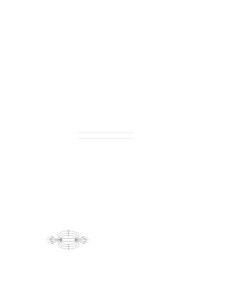
Properties of Magnetic Field Lines
get deflected when a current carrying metallic conductor is
The magnetic field lines have the following properties
placed nearby it. He concluded that the deflection of
compass needle was due to the magnetic field produced by
● They originate from North pole of a magnet and end at its
the electric current.
South pole, by convention.
Hence, it was deduced that electricity and magnetism are
● These lines are closed and continuous curves.
related to each other.
● They are crowded near the poles, where the magnetic field
is strong and separated far from the poles, where the
magnetic field is weak.
Magnetic Field
● Field lines never intersect with each other. If they do, that
It is the space around a magnet in which its effect can be
would mean that there are two directions of the magnetic
experienced i.e. its force can be detected. It is a vector
field at the point of intersection, which is impossible.
quantity. The SI unit of magnetic field is Tesla.
Magnetic Field due to a Current
Magnetic Lines of Force
They are the imaginary lines representing magnetic field
Carrying Conductor
around a magnet. When iron fillings are kept near a magnet,
When electric current flows through a metallic conductor, a
they get arranged in a pattern which represents the magnetic
magnetic field is produced around it.
field lines.
Different magnetic field patterns are produced by current
carrying conductors of different shapes.
S
N
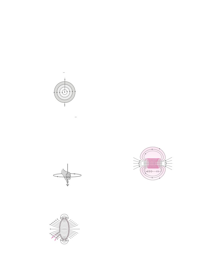
Magnetic Field due to a Current through
a Straight Conductor
Magnetic field lines around a bar magnet
The magnetic field lines around a current carrying
A compass needle behaves as a small bar magnet whose one
straight conductor are concentric circles whose centres lie
on the wire.
end points towards North and other end towards South.
The magnitude of magnetic field B produced by a straight
At every point on a current carrying circular loop, the
current carrying wire at a given point is
magnetic field is in the form of concentric circles around it.
As we move away from it, the circles would become larger
(i) Directly proportional to the current I passing through
and larger.
the wire,
When we reach the centre of loop, the field appears to be a
i.e.
B∝I
…(i)
straight line. The magnetic field produced by current
(ii) Inversely proportional to the distance r from the current
carrying circular wire at a given point is
carrying conductor,
(i) Directly proportional to the amount of current (I )
i.e.
B∝1
…(ii)
passing through it,
r
i.e.
B∝I
...(i)
I
(ii) Directly proportional to the number of turns (N) of the
wire,
i.e.
B∝N
...(ii)
This is because the current in each turn is in the same
direction. Therefore, the field due to these turns get
added up.
I
Thus, the strength of magnetic field produced by a
Concentric field lines around a straight conductor
current carrying circular coil can be increased by
● increasing the number of turns of the coil.
I
By using Eqs. (i) and (ii), we get, B
∝
● increasing the current flowing through the coil.
r
If the direction of current in a straight wire is known, then the
Magnetic Field due to a Current
direction of magnetic field produced by it is obtained by
in a Solenoid
Maxwell’s right hand thumb rule.
A solenoid is defined as a coil consisting of a large number
Maxwell’s Right Hand Thumb Rule
of circular turns of insulated copper wire. These turns are
wrapped closely to form a cylinder.
It states that, if you hold the current carrying straight wire in
the grip of your right hand in such a way that the stretched
thumb points in the direction of current, then the direction of
the curl of the fingers will give the direction of the magnetic
field. This rule is also called Maxwell’s corkscrew rule.
S
N
+
-
K
Magnetic field
Current
Magnetic field lines of force due to a current
carrying solenoid
Maxwell’s right hand thumb rule
The field lines around a current carrying solenoid are
similar to that produced by a bar magnet. This means that a
Magnetic Field due to a Current
current carrying solenoid behaves as if it has North pole and
through a Circular Loop
South pole. The field lines inside the solenoid are parallel to
The magnetic field lines due to a circular coil are shown in the
each other.
given figure.
Thus, the strength of magnetic field is the same, i.e. uniform
at all points inside a solenoid.
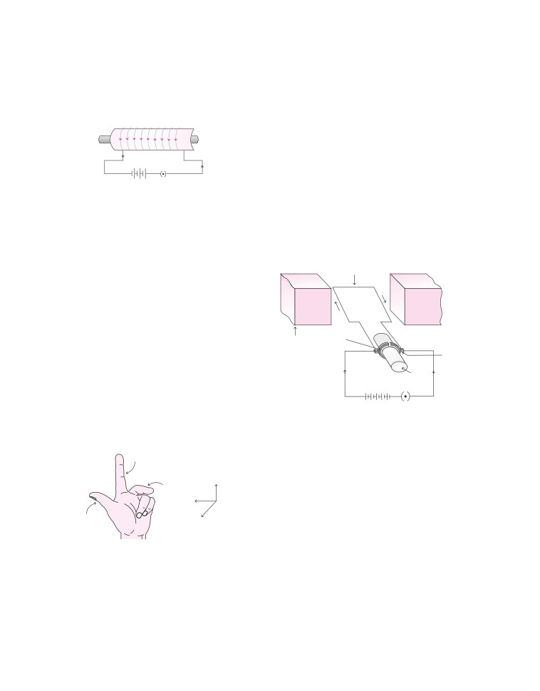
Electromagnet
The strong magnetic field produced inside a solenoid can be
N
S
used to magnetise a piece of magnetic material like soft iron
when placed inside the coil. The magnet so formed is called
-
electromagnet.
+
The magnetic effect remains only till the current is flowing
Magnetic field lines due to a
through the solenoid.
current through a circular loop
An electromagnet is used in electric bells, electric
Electric Motor
motors, telephone diaphragms, loudspeakers and for
It is a rotating device used for converting electric energy into
sorting scrap metal.
mechanical energy.
Principle
It is based on the principle that when a rectangular coil is placed
in a magnetic field and current is passed through it, two equal and
-
+
K
opposite forces act on the coil which rotate it continuously.
Construction
An electromagnet
It consists of a rectangular coil, connected to a source of current
Force on a Current Carrying
and a switch.
Conductor in a Magnetic Field
The commutators R1 and R2 are fixed to the coil and pressed
tightly against the brushes X and Y.
When a current carrying conductor is placed in a
magnetic field, it experiences a force. The force acting is
The function of commutator is to reverse the direction of current
due to interaction between magnetic field produced by
flowing through the coil, after every half rotation. In an electric
motor, split rings act as commutator.
the current carrying conductor and external magnetic
field in which the conductor is placed.
Rectangular coil
The direction of force on the conductor depends on the
B
C
following factors
(i) Direction of current The direction of force on the
N
S
conductor can be reversed by reversing the
direction of current.
A
D
(ii) Direction of magnetic field The direction of force
Split rings
R2
on the conductor can be reversed by reversing the
Permanent
R1
magnet
(R1 and R2)
Y
direction of magnetic field by interchanging the
Brushes
X
position of poles.
(X and Y )
Force on the conductor is maximum when the direction
Axle
of current is at right angles to the direction of magnetic
K
field.
+
-
Fleming’s Left Hand Rule
A simple electric motor
Working
The direction of force which acts on a current carrying
● Let coil ABCD be in horizontal position. When the key is
conductor placed in a magnetic field is given by Fleming’s
closed, the current flows in the coil ABCD through brush X and
left hand rule.
flows back to the battery through the brush Y via ring R2 .
Field
● No force acts on arms BC and ADas they are parallel to magnetic
field. Arm AB experiences a force in downward direction and arm
Field
CDexperiences an equal force in upward direction.
Current
● The direction of force is obtained by applying Fleming’s left
Force
hand rule. This causes the coil to rotate in the anti-clockwise
direction.
Force
Current
● When the rotating coil is in the vertical position, the brushes
or
motion
lose contact with the rings and current stops flowing. But the
coil does not stop due to inertia of motion.
Fleming’s left hand rule
● When the coil rotates, the rings change their positions and
come in contact with opposite brushes.
It states that, if the forefinger, thumb and middle
finger of left hand are stretched mutually perpendicular
● This reverses the direction of current through the coil but the
to each other, such that the forefinger points along
direction of current on right hand side of the coil remains the
the direction of external magnetic field, middle
same.
finger indicates the direction of current, then the
● So, the force on right hand side is always upwards and a force on
thumb points towards the direction of force acting on
left hand side is always in downward direction. Thus, the coil
the conductor.
continues to rotate in anti-clockwise direction.
The speed of rotation of the motor can be increased by
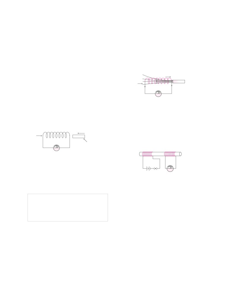
Ways to Induce Current in a Circuit
● increasing the strength of the current in the coil.
There are different methods by which current can be
● increasing the number of turns in the coil.
induced in a circuit
● increasing the area of the coil.
(i)
By Moving a Coil in a Magnetic Field Current can
● increasing the strength of magnetic field.
be induced in coil either by moving it in a magnetic
Commercial Electric Motor
field or by changing the magnetic field around it as
indicated by deflection in galvanometer needle.
It has the following components
● An electromagnet in the place of permanent magnet.
Motion of coil
Stationary
magnet
● A large number of turns of conducting wire in the current
Coil
N
S
carrying coil.
● A soft iron core on which the coil is wound. The combination
of soft iron core and coil is called armature. It enhances the
power of motor.
G
● Electric motor is used in electric fans, refrigerators, mixers,
Moving coil towards stationary magnet
washing machines, computers, MP3 players, etc.
The induced current is found to be maximum when
the direction of motion of the coil is at right angle
Electromagnetic Induction
to the magnetic field.
Production of an electric current in a closed circuit by a
The direction of induced current can be reversed by
changing magnetic field is called an induced current. This
reversing the direction of magnetic field. If the coil as
phenomenon is called electromagnetic induction.
well as the magnet are stationary, then no current is
induced in the coil.
Direction of motion
(ii)
By Changing the Magnetic Field Around a Nearby
Coil
N
S
Coil Consider two coils, where coil 1 is called as
A bar magnet
primary coil and coil 2 as secondary coil. Primary coil
is connected to a battery.
G
Galvanometer
Coil 1
Coil 2
A bar magnet is pushed inside a fixed current carrying coil
Fleming’s Right Hand Rule
+
-
The direction of induced current is given by Fleming’s right hand
G
K
rule. It states that, if the forefinger, middle finger and thumb of the
Set up of two stationary coils, where current is
right hand are stretched at right angles to each other, with the
induced in coil 2 when current in coil 1 is changed
forefinger in the direction of the magnetic field and the thumb in
the direction of the motion of the wire, then the induced current in
When the key (K) is closed, the current in primary coil
takes a little time to rise from zero to a maximum
the wire is in the direction of the middle finger.
value. This causes a momentary change in the
Galvanometer
magnetic field around this coil. This induces a
momentary current in the secondary coil.
It is an instrument that can detect the presence of current in a
circuit. The pointer remains at zero (the centre of the scale) for
The same happens in the reverse direction when the
zero current flowing through it.
key (K) is opened. Current is induced in coil 2 when
Depending upon the direction of current, it deflects either to
current in coil 1 is changed which is indicated by the
the left or to the right of the zero mark.
deflection in galvanometer needle.