The Experiments of Faraday and Henry
Discovery and understanding of electromagnetic induction are based on a long series of experiments carried out by Henry and Faraday.
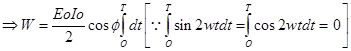
Experiment 1:
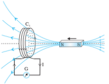
Image Source: NCERT Textbooks
If North-pole of a bar magnet is pushed towards the coil, the pointer in the galvanometer deflects, indicating the presence of electric current in the coil. This deflection lasts as long as the bar magnet remains in motion.
The galvanometer doesn’t show any deflection when the magnet is held at rest. When the magnet is pulled away from the coil, the galvanometer shows deflection in the opposite direction, which indicates reversal of the current’s direction.
This shows that the relative motion between the magnet and the coil that is responsible for generation (induction) of electric current in the coil.
Experiment 2:
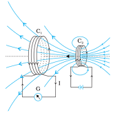
Image Source: NCERT Textbooks
If the bar magnet is replaced by a second coil C2 (as shown in figure given above) connected to a battery. The steady current in the coil C2 produces a steady magnetic field.
If coil C2 is moved towards the coil C1, then the galvanometer shows a deflection. This indicates that electric current is induced in coil C1.
When C2 is moved away, the galvanometer shows a deflection again, but this time in the opposite direction. The deflection will be observed as long as coil C2 is in motion.
When the coil C2 is held fixed and C1 is moved, the same effects are observed. Again, it is the relative motion between the coils that induces the electric current.
Experiment 3:
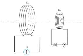
Image Source: NCERT textbooks
Faraday showed that this relative motion is not an absolute requirement. Figure given above shows two coils C1 and C2 held stationary. Coil C1 is connected to galvanometer G while the second coil C2 is connected to a battery through a tapping key K.
The galvanometer shows a momentary deflection when the tapping key K is pressed. The pointer in the galvanometer returns to zero immediately. If the key is held pressed continuously, there is no deflection in the galvanometer. When the key is released, a momentory deflection is observed again, but in the opposite direction. It is also observed that the deflection increases dramatically when an iron rod is inserted into the coils along their axis.
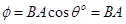
Magnetic Flux:
It is the number of magnetic field lines crossing any surface normally is called magnetic flux (ϕ) through that surface.
ϕ = B.A cos θ
Where B is magnetic field, A is are of the surface, ϕ is the angle between the magnetic field and area vector. SI unit of magnetic flux is weber.
Electromagnetic Induction:
It is the phenomenon of production of e.m.f. in a conductor due to a change in magnetic flux linked with it. The e.m.f so produced is called induced e.m.f. and current is called induced current.
Faraday’s Law of Electromagnetic Induction:
The magnitude of the induced emf in a circuit is equal to the time rate of change of magnetic flux through the circuit. Mathematically, the induced emf is given by ε = ‒ (dϕ/dt).
Negative sign shows that the current induced in a circuit always flows in such a direction that it opposes the change or the cause that it opposes the change or the cause produces it.
In the case of a closely wound coil of N turns, change of flux associated with each turn, is the same. Therefore, the expression for the total induced emf is given by
ε = ‒ N (dϕ/dt)
The induced emf can be increased by increasing the number of turns N of a closed coil.
The flux can be varied by changing any one or more of the terms B, A and θ.
Lenz’s Law and Conservation of Energy
The polarity of induced emf is such that it tends to produce a current which opposes the change in magnetic flux that produced it.
ε = ‒ N (dϕ/dt)
The negative sign shown in this equation represents this effect.
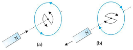
Image Source: NCERT textbooks
In the above figure (a), when the North-pole of a bar magnet is being pushed towards a closed coil the magnetic flux through the coil increases. Hence current is induced in the coil in such a direction that it opposes the increase in flux. This is possible only if the current in the coil is in a counter-clockwise direction with respect to an observer situated on the side of the magnet. Vice versa case is shown in figure (b).
Lenz’s law complies with the principle of conservation of energy. Here when the N-pole of a bar magnet is pushed into a coil as shown, the direction of induced current in the coil will act as N-pole. So, work has to be done against the magnetic repulsive force to push the magnet into the coil. The electrical energy produced in the coil as the expense of this work done
Motional Electromotive Force
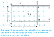
Image Source: NCERT textbooks
Suppose a straight conductor moving in a uniform and time independent magnetic field. In the figure given above induced e.m.f. is given by ε = ‒ [d(Blx)/dt] = Blv {where dx/dt = –v}.
Eddy Currents
The currents induced in body of a conductor when the amount of magnetic flux linked with the conductor changes.
Applications of Eddy Currents
Electromagnetic damping
Some galvanometers have a fixed core made of nonmagnetic metallic material. When the coil oscillates, the eddy currents are generated in the core which opposes the motion & bring the coil to rest quickly.
Induction furnace
Induction furnaces are used to produce high temperatures & generally used to prepare alloys, by melting the constituent metals. When a high frequency alternating current passes through the coil (which surrounds the metal) then eddy currents are produced in the metal which in turn produce high temperatures and melts the metal.
Magnetic braking in trains
Strong electromagnets are situated above the rails in electrically powered trains. When the electromagnets are activated, the eddy currents induced in the rails oppose the motion of the train.
Electric Power Meters
You must have observed the rotating shiny disc in the power meter of your house. The shiny metal disc in the electric power meter rotates due to the eddy currents. Electric currents are induced in the disc by magnetic fields produced by alternating currents in a coil.
Inductance
Electric current can be induced in a coil by flux change produced by another coil in its vicinity or flux change produced by the same coil. These two situations are described separately in the next two sub-sections. In both the cases, the flux through a coil is proportional to the current, i.e., ϕB ∝ I.
If the geometry of the coil does not vary with time then, d(ϕB)/dt ∝ d(I)/dt.
For a closely wound coil of N turns, the same magnetic flux is linked with all the turns.
Therefore, a term called flux linkage is used which is equal to NϕB for a closely wound coil and in such a case NϕB ∝ I.
The constant of proportionality, in this relation, is called inductance. In inductance depends only on geometry of coil and intrinsic properties of a material.
Self Inductance
It is the property of a coil by virtue of which, the coil opposes any change in the strength of current flowing through it by inducing e.m.f. in itself.
Coefficient of Self Inductance
If I is the magnitude of current flowing through a coil at any time, ϕ amount of magnetic flux linked with all the turns of coil at that time, then, ϕ ∝ I or ϕ = L I
Where, L is a constant of proportionality and also known as coefficient of self inductance or coefficient of self inductance.
If I = 1 then, ϕ = L I or L = ϕ. So, self inductance of a coil is numerically equal to the magnetic flux linked with the coil when unit current flows through the coil.
With slight modification of above formula, one can also say that, self inductance of a coil is numerically equal to the e.m.f. induced in the coil when the rate of change of current through the coil is unity.
SI unit of self inductance is equal to the henry (H).
Self Inductance of a Long Solenoid
If L is the inductance of a long air-cored coil of length l, having n turns per length of cross sectional area A each then, L = μo n2lA
Mutual Inductance
It is the property by virtue of which two closely lying coils opposes any change in the strength of current flowing through the other by developing an induced e.m.f.
Coefficient of Mutual Inductance
If I is the strength of the current in one coil, ϕ is the amount of magnetic flux linked with all the turns of neighbouring coil, then, ϕ ∝ I or ϕ = MI
Where, M is constant of proportionality and is called coefficient of mutual or mutual inductance.
If I = 1, ϕ = M × 1 or M = ϕ
Where, M is a constant of proportionality and also known as coefficient of mutual induction.
Coefficient of mutual induction or mutual induction of two coils is numerically equal to the amount of magnetic flux linked with one coil when unit amount of current flows through the neighbouring coil.
SI unit to measure mutual inductance is henry (H).
Factors affecting Mutual Inductance of a Pair of Coil
• Geometry of two coils such as shape, size, number of turns and nature of material
• Relative placement or orientation of two coils
AC Generator
It is a device which converts mechanical energy into electrical energy. It works on the principle of electromagnetic induction. The main components of AC dynamo are field magnet, armature, slip rings and brushes.
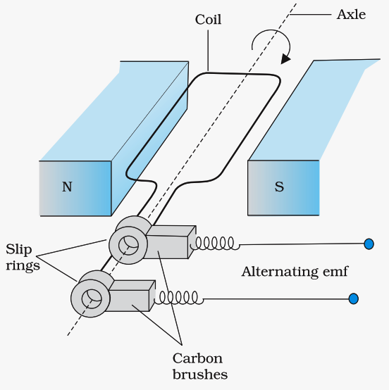
Image Source: NCERT Textbook
Instantaneous value of induced e.m.f, is by ε = n B A ω sin ω t, where, n is the number of turns of the coil, A is the area of the coil, B is the magnetic field strength. If we denote NBAω as ε0, then ε = ε0 sin ωt.
Since, ω = 2πν, so we can also write can be written as ε = ε0 sin 2π ν t where ν is the frequency of revolution of the generator’s coil. The instantaneous value of the emf and ε varies between +ε0 and –ε0 periodically.
CBSE Class 12 Physics Important Questions Chapter 6 – Electromagnetic Induction
1 Mark Questions
1. A metallic wire coil is stationary in a non – uniform magnetic field. What is the emf. Induced in the coil?
Ans. NO emf is induced in the coil as there is no change in the magnetic flux linked with the secondary coil.
2. Why does metallic piece becomes very hot when it is surrounded by a coil carrying high frequency (H.F) alternating current?
Ans. When a metallic piece is surrounded by a coil carrying high frequency (H.F) alternating current, it becomes hot because eddy currents are produced which in turn produces joule’s heating effect.
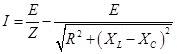
3. An electrical element X when connected to an alternating voltage source has current through it leading the voltage by  radian. Identify X and write expression for its reactance?
Ans. X is a purely capacitive circuit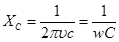
4. A transformer steps up 220 V to2200 V. What is the transformation ratio?
Ans. 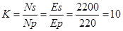
5. The induced emf is also called back emf. Why?
Ans. it is because induced emf produced in a circuit always opposes the cause which produces it.
6. Why the oscillations of a copper disc in a magnetic field are lightly damped?
Ans. Copper disc oscillates because of the production of eddy currents which opposes its oscillating motion and as a result the motion gets damped.
7.A metallic wire coil is stationary in a non – uniform magnetic field. What is the emf. Induced in the coil?
Ans.NO emf is induced in the coil as there is no change in the magnetic flux linked with the secondary coil.
2 Marks Questions
1. IF the rate of change of current of 2A/s induces an emf of 1OmV in a solenoid. What is the self-inductance of the solenoid?
Ans.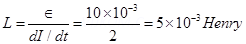


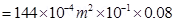
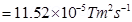
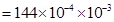
2. A circular copper disc. 10 cm in radius rotates at a speed of 2  rad/s about an axis through its centre and perpendicular to the disc. A uniform magnetic field of 0.2T acts perpendicular to the disc.
1) Calculate the potential difference developed between the axis of the disc and the rim.
2) What is the induced current if the resistant of the disc is 2  ?
?
Ans. (1) Radius = 10cm, B = 0.2T w = 2 rad/s
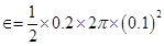


I = 0.0314 A
3. An ideal inductor consumes no electric power in a.c. circuit. Explain?
Ans. P = E rms I rms cos 
But for an ideal inductor 
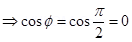 P=0
P=0
4. Capacitor blocks d.c. why?
Ans. The capacitive reactance
For d.c.  = 0
= 0
Since capacitor offers infinite resistance to the flow of d.c. so d.c. cannot pass through the capacitor.
5. Why is the emf zero, when maximum number of magnetic lines of force pass through the coil?
Ans. The magnetic flux will be maximum in the vertical position of the coil. But as the coil rotates 
Hence produced emf 
6. An inductor L of reactance  is connected in series with a bulb B to an a.c. source as shown in the figure.
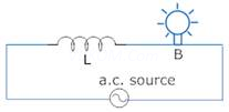
Briefly explain how does the brightness of the bulb change when
(a) Number of turns of the inductor is reduced.
(b) A capacitor of reactance  is included in series in the same circuit.
Ans. (a) Since Z = 
When number of turns of the inductor gets reduced and Z decreases and in turn current increases
Hence the bulb will grow more brightly
(b) When capacitor is included in the circuit
But  (given)Z = R (minimum)
Hence brightness of the bulb will become maximum.
7. A jet plane is travelling towards west at a speed of 1800 km/h. What is the voltage difference developed between the ends of the wing having a span of 25 m, if the Earth’s magnetic field at the location has a magnitude of  and the dip angle is
Ans. Speed of the jet plane, v = 1800 km/h = 500 m/s
Wing span of jet plane, l = 25 m
Earth’s magnetic field strength, B = 
Angle of dip,  s
s
Vertical component of Earth’s magnetic field,
BV = B sin
= 
= 
Voltage difference between the ends of the wing can be calculated as:
=
= 3.125 V
Hence, the voltage difference developed between the ends of the wings is
3.125 V.
8. A pair of adjacent coils has a mutual inductance of 1.5 H. If the current in one coil changes from 0 to 20 A in 0.5 s, what is the change of flux linkage with the other coil?
Ans. Mutual inductance of a pair of coils, µ = 1.5 H
Initial current,  = 0 A
= 0 A
Final current  = 20 A
Change in current, 
Time taken for the change, t = 0.5 s
Induced emf, 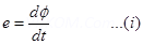
Where  is the change in the flux linkages with the coil.
Emf is related with mutual inductance as:
Equating equations (1) and (2), we get


Hence, the change in the flux linkage is 30 Wb.
9. A horizontal straight wire 10 m long extending from east to west is falling with a speed of  , at right angles to the horizontal component of the earth’s magnetic field,
  Wb
Wb  .
.
(a) What is the instantaneous value of the emf induced in the wire?
(b) What is the direction of the emf?
(c) Which end of the wire is at the higher electrical potential?
Ans. Length of the wire, l = 10 m
Falling speed of the wire, v = 5.0 m/s
Magnetic field strength, B = 
(a) Emf induced in the wire,
e = Blv

(b) Using Fleming’s right hand rule, its can be inferred that the direction of the induced emf is from West to East.
(c) The eastern end of the wire is at a higher potential.
10. A 1.0 m long metallic rod is rotated with an angular frequency of 400 rad  about an axis normal to the rod passing through its one end. The other end of the rod is in contact with a circular metallic ring. A constant and uniform magnetic field of 0.5 T parallel to the axis exists everywhere. Calculate the emf developed between the centre and the ring.
Ans. Length of the rod, l = 1 m
Angular frequency, = 400 rad/s
Magnetic field strength, B = 0.5 T
One end of the rod has zero linear velocity, while the other end has a linear velocity of .
.
Average linear velocity of the rod,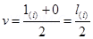
Emf developed between the centre and the ring,
Hence, the emf developed between the centre and the ring is 100 V.
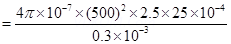
11. Use Lenz’s law to determine the direction of induced current in the situations described by Fig. 6.19:
(a) A wire of irregular shape turning into a circular shape;
(b) A circular loop being deformed into a narrow straight wire.
Ans. According to Lenz’s law, the direction of the induced emf is such that it tends to produce a current that opposes the change in the magnetic flux that produced it.
(a) When the shape of the wire changes, the flux piercing through the unit surface area increases. As a result, the induced current produces an opposing flux. Hence, the induced current flows along adcb.
(b) When the shape of a circular loop is deformed into a narrow straight wire, the flux piercing the surface decreases. Hence, the induced current flows along 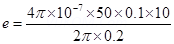


3 Marks Questions
1. How is the mutual inductance of a pair of coils affected when
(1) Separation between the coils is increased.
(2) The number of turns of each coil is increased.
(3) A thin iron sheet is placed between two coils, other factors remaining the same. Explain answer in each case.
Ans. (1) When the Separation between the coils is increased, the flux linked with the
secondary coils decreases, hence mutual induction decreases.
(2) Since m = so when
  increases, mutual induction increase.
(3) Mutual induction will increase because (Relative permeability of material)
2. Distinguish between resistances, reactance and impedance of an a.c. circuit?
Ans.
| Resistance | Reactance | Impedance | |
| 1 | Opposition offered by the resistor to the flow of current | Opposition offered by the inductor or capacitor to the flow of current | Opposition offered by the combination of resistor, inductor or capacitor |
| 2 | It is independent of the frequency of the source. | It depends on the frequency of the source | It depends on the frequency of the source |
3. A sinusoidal voltage V = 200 sin 314t is applied to a resistor of 10  resistance. Calculate
(1) rms value of the voltage
(2) rms value of the current
(3) Power dissipated as heat in watt.
Ans. V = 200 sin 314t
V = Vo sin wt
Vo = 200V, w = 314 rad/s.
R = 10
(1) V rms = 
V rms =  200 = 282.8 V
(2) 
I rms = 28.28 A
(3) Since circuit is purely resistive


P = 7.998 watt
4. Obtain an expression for the self inductance of a long solenoid? Hence define one Henry?
Ans. Consider a long solenoid of area A through which current I is flowing
Let N be the total number of turns in the solenoid
Total flux  = NBA
= NBA
Here = B = 
Where n is no. of turns per unit length of the solenoid
N = nl
Equation (1) & (2)


 [n = N/
 ]
]
One Henry – if current is changing at a rate of 1 A/s in a coil induces an emf. of 1 volt in it then the inductance of the coil is one henry.
5. A conducting rod rotates with angular speed w with one end at the centre and other end at circumference of a circular metallic ring of radius R, about an axis passing through the centre of the coil perpendicular to the plane of the coil A constant magnetic field B parallel to the axis is present everywhere. Show that the emf. between the centre and the metallic ring is 
Ans. Consider a circular loop connect the centre with point P with a resistor.
The potential difference across the resistor = induced emf. Rate of change of area of loop.
If the resistor QP is rotated with angular velocity w and turns by an angle  in time t then
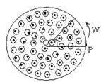
Area swept 


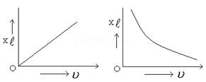
6. (a) At a very high frequency of a.c., capacitor behaves as a conductor. Why?
(b) Draw the graph showing the variation of reactance of
(i) A capacitor
(ii) An inductor with a frequency of an a.c. circuit.
Ans. (a) 
For a.c. when 

Thus at a very high frequency of a.c. capacitor behaves as a conductor
(b) 


7. Calculate the current drawn by the primary of a transformer which steps down 200 V to 20 V to operate a device of resistance 20  . Assume the efficiency of the transformer to be 80%?
Ans. = 80% Ep = 200V Es = 20V Z = 20
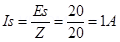

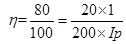

Ip = 0.125 A
8. An a.c. voltage E = Eo sin wt is applied across an inductance L. obtain the expression for current I?
Ans.E = Eo sin wt (Given)
Emf produced across L = 
Total emf of the circuit = 
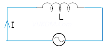
Since there is no circuit element across which potential drop may occur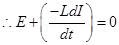


Integrating

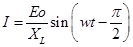
 (peak vlue of current)I = Io sin
9. A series circuit with L = 0.12H, C = 0.48mF and R = 25 is connected to a 220V variable frequency supply. At what frequency is the circuit current maximum?
Ans.L = 0.12H, C = 0.48mF = 
R = 25 Ev = 220V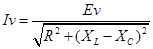
In the circuit when I is maximum, R will be minimum

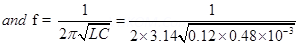
f = 21 Hz
10. A rectangular wire loop of sides 8 cm and 2 cm with a small cut is moving out of a region of uniform magnetic field of magnitude 0.3 T directed normal to the loop. What is the emf developed across the cut if the velocity of the loop is  in a direction normal to the (a) longer side, (b) shorter side of the loop? For how long does the induced voltage last in each case?
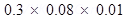
Ans. Length of the rectangular wire, l = 8 cm = 0.08 m
Width of the rectangular wire, b = 2 cm = 0.02 m
Hence, area of the rectangular loop,
A = lb

Magnetic field strength, B = 0.3 T
Velocity of the loop, v = 1 cm/s = 0.01 m/s
(a) Emf developed in the loop is given as:
e = Blv
=

Time taken to travel along the width. ts

Hence, the induced voltage is  which lasts for 2 s.
(b) Emf developed, e = Bbv
= 
Time taken to travel along the length,
t

Hence, the induced voltage is which lasts for 8 s.
11. Current in a circuit falls from 5.0 A to 0.0 A in 0.1 s. If an average emf of 200 V induced, give an estimate of the self-inductance of the circuit.
Ans. Initial current, 
Final current, 
Change in current,
Time taken for the change, t = 0.1
Average emf, e = 200 V
For self-inductance (L) of the coil, we have the relation for average emf as:
e = L  s
s


 s
s
Hence, the self-induction of the coil is 4 H.
12. Suppose the loop in Exercise 6.4 is stationary but the current feeding the electromagnet that produces the magnetic field is gradually reduced so that the field decreases from its initial value of 0.3 T at the rate of  . If the cut is joined and the loop has a resistance of 1.6 how much power is dissipated by the loop as heat? What is the source of this power?
Ans. Sides of the rectangular loop are 8 cm and 2 cm.
Hence, area of the rectangular wire loop,


Initial value of the magnetic field, 
Rate of decrease of the magnetic field, 
Emf developed in the loop is given as:
Where,= Change in flux through the loop area
= AB
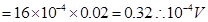
Resistance of the loop, R = 1.6
The current induced in the loop is given as:
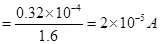
Power dissipated in the loop in the form of heat is given as:


The source of this heat loss is an external agent, which is responsible for changing the magnetic field with time.
13. An air-cored solenoid with length 30 cm, area of cross-section  and number of turns 500, carries a current of 2.5 A. The current is suddenly switched off in a brief time of
  . How much is the average back emf induced across the ends of the open switch in the circuit? Ignore the variation in magnetic field near the ends of the solenoid.
Ans. Length of the solenoid, l = 30 cm = 0.3 m
Area of cross-section, A = 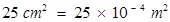
Number of turns on the solenoid, N = 500
Current in the solenoid, I = 2.5 A
Current flows for time, t =  s
s
Average back emf, 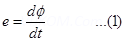
Where,= Change in flux
= NAB ……(2)
Where,
B = Magnetic field strength
Where, = Permeability of free space =
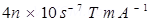
Using equations (2) and (3) in equation (1), we get

Hence, the average back emf induced in the solenoid is 6.5 V.
14. A line charge  per unit length is lodged uniformly onto the rim of a wheel of mass M and radius R. The wheel has light non-conducting spokes and is free to rotate without friction about its axis (Fig. 6.22). A uniform magnetic field extends over a circular region within the rim. It is given by,
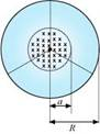
 = 0 (otherwise) What is the angular velocity of the wheel after the field is suddenly switched off?
Ans. Line charge per unit length
Where,
r = Distance of the point within the wheel
Mass of the wheel = M
Radius of the wheel = R
Magnetic field, 
At distance r, the magnetic force is balanced by the centripetal force i.e.,
Where
V=linear velocity of the wheel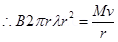

∴ Angular velocity, 

5 Marks Questions
1. (a) State the condition under which the phenomenon of resonance occurs in a series LCR circuit. Plot a graph showing the variation of current with frequency of a.c. sources in a series LCR circuit.
(b) Show that in a series LCR circuit connected to an a.c. source exhibits resonance at its natural frequency equal to 
Ans. (a) In a series LCR circuit
Resonance occurs when 
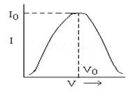
The variation of current with frequency of a.c. source in series LCR circuit
(b) Electrical resonance takes place in a series LCR circuit when circuit allows maximum alternating current for which
Impedance Z = 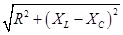
For electrical resonance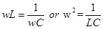

Where w is the natural frequency of the circuit.
2. In a step up transformer, transformation ratio is 100. The primary voltage is 200 V and input is 1000 watt. The number of turns in primary is 100. Calculate
(1) Number of turns in the secondary
(2) Current in the primary
(3) The voltage across the secondary
(4) Current in the secondary
(5) Write the formula for transformation ratio?
Ans. (1) k = 100, Ep = 200V
EpIp = 1000 W, Np = 100


NS = 10,000
(2) EpIp = 1000W

Ip = 5A
(3) 
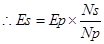

Es = 20000 Volt
(4) 


Is = 0.05 A
(5) For step up Trans former k > 1 
3. Drive an expression for the average power consumed in a.c. series LCR circuit. Hence define power factor?
Ans. For an a.c. series circuit
E = Eo sin wt
And I = Io sin (wt + )
)
Where is the phase angle by which current leads the emf.
Now using dw = EIdt
dw = (Eo sin wt) (Io sin (wt +) )dt
dw = EoIo sin wt (sin wt cos + cos wt sin)dt
dw = EoIo ( wt cos + sin wt cos wt sin)dt
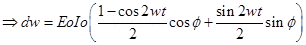
Integrating within limits t = o to t = T

Hence average power consumed in a.c circuit is given by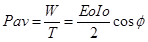
Pav = EvIv cos —–(1)
Power factor – In the above expression
Cos is termed as power factor
When cos = 1 = 
It means circuit is purely resistive and Pav = EvIv
When cos = 0 =
It means circuit is purely capacitive or inductive.
Pav = 0
Hence
4. Predict the direction of induced current in the situations described by the following Figs. 6.18(a) to (f ).
(a)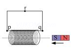
(b)
(c)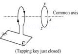
(d)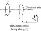
(e)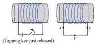
(f)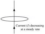
Ans. The direction of the induced current in a closed loop is given by Lenz’s law. The given pairs of figures show the direction of the induced current when the North pole of a bar magnet is moved towards and away from a closed loop respectively. Using Lenz’s rule, the direction of the induced current in the given situations can be predicted as follows: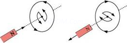
(a) The direction of the induced current is along qrpq.
(b) The direction of the induced current is along prqp.
(c) The direction of the induced current is along yzxy.
(d) The direction of the induced current is along zyxz.
(e) The direction of the induced current is along xryx.
(f) No current is induced since the field lines are lying in the plane of the closed loop.
5. A long solenoid with 15 turns per cm has a small loop of area 2.0  placed inside the solenoid normal to its axis. If the current carried by the solenoid changes steadily from 2.0 A to 4.0 A in 0.1 s, what is the induced emf in the loop while the current is changing?
Ans. Number of turns on the solenoid = 15 turns/cm = 1500 turns/m
Number of turns per unit length, n = 1500 turns
The solenoid has a small loop of area, A = 

Current carried by the solenoid changes from 2 A to 4 A. Change in current in the solenoid, di = 4 – 2 = 2 A
Change in time, dt = 0.1 s
Induced emf in the solenoid is given by Faraday’s law as: ……(i)
……(i)
Where, = Induced flux through the small loop
= BA …(ii)
B = Magnetic field
= 
 = Permeability of free space
Hence, equation (i) reduces to:

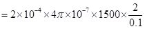

Hence, the induced voltage in the loop is 

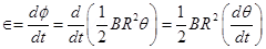
6. A circular coil of radius 8.0 cm and 20 turns is rotated about its vertical diameter with an angular speed of 50  in a uniform horizontal magnetic field of magnitude
  . Obtain the maximum and average emf induced in the coil. If the coil forms a closed loop of resistance
  , calculate the maximum value of current in the coil. Calculate the average power loss due to Joule heating. Where does this power come from?
Ans. Max induced emf = 0.603 V
Average induced emf = 0 V
Max current in the coil = 0.0603 A
Average power loss = 0.018 W
(Power comes from the external rotor)
Radius of the circular coil, r = 8 cm = 0.08 m
Area of the coil, 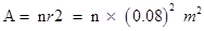
Number of turns on the coil, N = 20
Angular speed,  = 50 rad/s
Magnetic field strength, B = 
Resistance of the loop, R = 10 
Maximum induced emf is given as:
 = 0.603 V
The maximum emf induced in the coil is 0.603 V.
Over a full cycle, the average emf induced in the coil is zero.
Maximum current is given as:
Average power loss due to joule heating:
The current induced in the coil produces a torque opposing the rotation of the coil. The rotor is an external agent. It must supply a torque to counter this torque in order to keep the coil rotating uniformly. Hence, dissipated power comes from the external rotor.
7. A square loop of side 12 cm with its sides parallel to X and Y axes is moved with a velocity of  in the positive x-direction in an environment containing a magnetic field in the positive z-direction. The field is neither uniform in space nor constant in time. It has a gradient of
  along the negative x-direction (that is it increases by
  as one moves in the negative x-direction), and it is decreasing in time at the rate of
  . Determine the direction and magnitude of the induced current in the loop if its resistance is 4.50 .
Ans. Side of the square loop, s = 12 cm = 0.12 m
Area of the square loop, 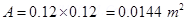
Velocity of the loop, v = 8 cm/s = 0.08 m/s
Gradient of the magnetic field along negative x-direction,
And, rate of decrease of the magnetic field,
Resistance of the loop, 
Rate of change of the magnetic flux due to the motion of the loop in a non-uniform magnetic field is given as:
Rate of change of the flux due to explicit time variation in field B is given as:

Since the rate of change of the flux is the induced emf, the total induced emf in the loop can be calculated as: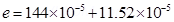

∴Induced current,  s
s
s

Hence, the direction of the induced current is such that there is an increase in the flux through the loop along positive z-direction.
8. It is desired to measure the magnitude of field between the poles of a powerful loud speaker magnet. A small flat search coil of area  with 25 closely wound turns, is positioned normal to the field direction, and then quickly snatched out of the field region. Equivalently, one can give it a quick
  turn to bring its plane parallel to the field direction). The total charge flown in the coil (measured by a ballistic galvanometer connected to coil) is 7.5 mC. The combined resistance of the coil and the galvanometer is 0.50 . Estimate the field strength of magnet.
Ans. Area of the small flat search coil, A = 
Number of turns on the coil, N = 25
Total charge flowing in the coil, Q = 7.5 mC = 
Total resistance of the coil and galvanometer, R = 0.50
Induced current in the coil,
Induced emf is given as:
Where, = Charge in flux
Combining equations (1) and (2), we get
Initial flux through the coil,  = BA
= BA
Where,
B = Magnetic field strength
Final flux through the coil, 
Integrating equation (3) on both sides, we have
But total charge, 


Hence, the field strength of the magnet is 0.75 T.
9. Figure 6.20 shows a metal rod PQ resting on the smooth rails AB and positioned between the poles of a permanent magnet. The rails, the rod, and the magnetic field are in three mutual perpendicular directions. A galvanometer G connects the rails through a switch K. Length of the rod = 15 cm, B = 0.50 T, resistance of the closed loop containing the rod = 9.0 m . Assume the field to be uniform.
(a) Suppose K is open and the rod is moved with a speed of  in the direction shown. Give the polarity and magnitude of the induced emf.
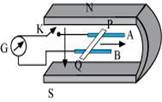
(b) Is there an excess charge built up at the ends of the rods when K is open? What if K is closed?
(c) With K open and the rod moving uniformly, there is no experience magnetic force due to the motion of the rod. Explain.
(d) What is the retarding force on the rod when K is closed?
(e) How much power is required (by an external agent) to keep the rod moving at the same speed (= ) when K is closed? How much power is required when K is open?
(f) How much power is dissipated as heat in the closed circuit? What is the source of this power?
(g) What is the induced emf in the moving rod if the magnetic field is parallel to the rails instead of being perpendicular?
Ans. Length of the rod, l = 15 cm = 0.15 m
Magnetic field strength, B = 0.50 T
Resistance of the closed loop, R = 9 =
(a) Induced emf = 9 mV; polarity of the induced emf is such that end P shows positive while end Q shows negative ends.
Speed of the rod, v = 12 cm/s = 0.12 m/s
Induced emf is given as:
e = Bvl
=  v
v
= 9 mV
The polarity of the induced emf is such that end P shows positive while end Q shows negative ends.
(b) Yes; when key K is closed, excess charge is maintained by the continuous flow of current.
When key K is open, there is excess charge built up at both ends of the rods.
When key K is closed, excess charge is maintained by the continuous flow of current.
(c) Magnetic force is cancelled by the electric force set-up due to the excess charge of opposite nature at both ends of the rod.
There is no net force on the electrons in rod PQ when key K is open and the rod is moving uniformly. This is because magnetic force is cancelled by the electric force set-up due to the excess charge of opposite nature at both ends of the rods.
(d) Retarding force exerted on the rod, F = IBl
Where,
I = Current flowing through the rod


(e) 9 mW; no power is expended when key K is open.
Speed of the rod, v = 12 cm/s = 0.12 m/s
Hence, power is given as:


When key K is open, no power is expended.
(f) 9 mW; power is provided by an external agent.
Power dissipated as heat = I2 R
= 
= 9 mW
The source of this power is an external agent.
(g) Zero In this case, no emf is induced in the coil because the motion of the rod does not cut across the field lines.
10. (a) Obtain an expression for the mutual inductance between a long straight wire and a square loop of side a as shown in Fig. 6.21.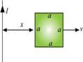
(b) Now assume that the straight wire carries a current of 50 A and the loop is moved to the right with a constant velocity, v = 10 m/s.
Calculate the induced emf in the loop at the instant when x = 0.2 m.
Take a = 0.1 m and assume that the loop has a large resistance.
Ans.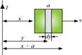
(a) Take a small element dy in the loop at a distance y from the long straight wire (as shown in the given figure).
Magnetic flux associated with element
Where,
dA = Area of element dy = a dy
B = Magnetic field at distance y s
s
I = Current in the wire= Permeability of free space =


y tends from x to a+x.s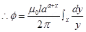
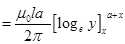
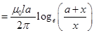
For mutual inductance M, the flux is given as:
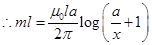
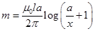
(b) Emf induced in the loop, e = B’av  Given,
I = 50 A
x = 0.2 m
a = 0.1 m
v = 10 m/s