Question
In cold weather, houses are often heated with an electrical heater.
Fig. 9.1 shows a simplified electrical circuit for a household heater.
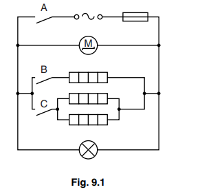
(a) What does the symbol ![]() represent?
represent?
…………………………………………………………………………………………………………………………….
(b) The heater has three identical heating elements, a fan driven by a motor and a lamp.
Name the components that are working when switch A only is closed.
…………………………………………………………………………………………………………………………….
(c) The heater has two switches, B and C, to give high, medium and low heat settings.
Identify how each heat setting is obtained. Complete the table by adding ticks to represent a closed switch.
|
heater settings |
switch B |
switch C |
|
high |
||
|
medium |
||
|
low |
(d) Write down the equation that relates resistance, potential difference (p.d.) and current.
…………………………………………………………………………………………………………………………….
(e) The current in one of the heating elements is 5.0 A. The resistance of the heating element is 50 Ω.
Calculate the p.d. across the heating element. Include the appropriate unit.
p.d. =…………………………………………………………………………………………………………………….
(f) Explain how the component with the symbol ![]() protects the circuit.
protects the circuit.
…………………………………………………………………………………………………………………………………
Answer/Explanation
Answer:
(a) alternating voltage OR a.c. (supply)
(b) motor (accept fan) AND lamp
(c) line 1 tick and then tick
line 2 cross/nothing and then tick
line 3 tick and then cross/nothing
(d) V=IR in any form
(e) 50×5
250 V
(f) any two from:
• current too large
• fuse wire melts/”blows”
• breaks circuit
• prevents overheating/fires/damage to other components
Question
Fig. 9.1 shows a series circuit. The resistances of the ammeter and of the battery may be ignored. 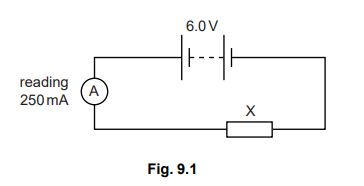
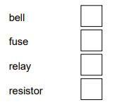
(a) What is component X? Tick one box. bell
(b) State the value of
(i) the e.m.f. of the battery, ……………………………………………………………………
(ii) the potential difference across component X, ……………………………………..
(iii) the current in the circuit. …………………………………………………………………..
(c) Use values from Fig. 9.1 to calculate the resistance of component X. Give the unit.
resistance =………………………………………
(d) A resistor R is connected in parallel with component X.
State what effect, if any, this has on
(i) the total resistance of the circuit,
………………………………………………………………………………………………………………….
(ii) the reading on the ammeter,
………………………………………………………………………………………………………………….
(iii) the current in component X.
………………………………………………………………………………………………………………….
Answer/Explanation
Answer:
(a) resistor
(b) (i) 6.0V OR 6V, unity penalty applies
(ii) 6.0V OR 6V, unity penalty applies unless penalised in (i), no e.c.f. from (i)
(iii) 250mA OR 0.25 A, unit penalty applies unless penalised in (i) or (ii)
(c) (R =) V/I
6/0.25 OR 6/250
24 OR 0.024
Ω OR ohm(s) OR kΩ (note: if value calculated, unit must agree with value)
(d) (i) decreases
(ii) increases
(iii) unchanged
accept no effect/none
Question
Fig. 11.1 shows an electron beam about to enter, at point A, the electric field between two charged metal plates.
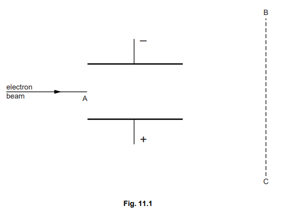
(a) On Fig. 11.1, carefully draw the path of the electron beam between A and the line BC. [3]
The voltage across the plates is reversed. State what difference this makes to the path of the electron beam.
…………………………………………………………………………………………………………………………
……………………………………………………………………………………………………………………. [1] [Total: 4]
Answer/Explanation
Ans: (a) any downward deflection and no upward deflection curve, either all up or all down, from A to end of region between plates straight on from end of region between plates, towards BC (b) idea of deflection upwards/it goes upwards/it moves upwards no e.c.f.ignore opposite direction/opposite path