Topics covered in this chapter:
Notes:
electric current $(I)$ : the flow of charged particles through a conductor, caused by a difference in electric potential. The direction of the electric current is defined as the direction that a positively-charged particle would move. Note, however, that the particles that are actually moving are electrons, which are negatively charged.
This means that electric current “travels” in the opposite direction from the electrons. We will use conventional current (pretending that positive particles are flowing through the circuit) throughout this course.
Electric current $(\overrightarrow{\boldsymbol{I}})$ is a vector quantity and is measured in amperes (A), often abbreviated as “amps”. One ampere is one coulomb per $I=\frac{\Delta Q}{t}$ second.
Note that when electric current is flowing, charged particles move from where they are along the circuit. For example, when a light bulb is illuminated, the electrons that do the work for the first few minutes are already in the filament.
voltage (potential difference) $(\Delta V)^*$ : the difference in electric potential energy between two locations, per unit of charge.
$\Delta V=\frac{W}{q}$
Potential difference is the work $(W)$ done on a charge per unit of charge $(q)$.
Potential difference $(\Delta V)$ is a scalar quantity (in DC circuits) and is measured in volts (V), which are equal to joules per coulomb.
The total voltage in a circuit is usually determined by the power supply that is used for the circuit (usually a battery in DC circuits). circuit.
resistance $(R)$ : the amount of electromotive force (electric potential) needed to force a given amount of current through an object in a DC
$R=\frac{\Delta V}{I}$ circuit.
Resistance $(R)$ is a scalar quantity and is measured in ohms $(\Omega)$. One ohm is one volt per ampere.
This relationship is Ohm’s Law, named for the German physicist Georg Ohm. Ohm’s Law is more commonly written:
$I=\frac{\Delta V}{R} \quad$ or $\quad \Delta V=I R$
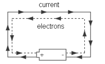
Simply put, Ohm’s Law states that an object has an ability to resist electric current flowing through it. The more resistance an object has, the more voltage you need to force electric current through it. Or, for a given voltage, the more resistance an object has, the less current will flow through it. Resistance is an intrinsic property of a substance. In this course, we will limit problems that involve calculations to ohmic resistors, which means their resistance does not change with temperature.
* Note that most physics texts (and most physicists and electricians) use V for both electric potential and voltage, and students have to rely on context to tell the difference. In these notes, to make the distinction clear (and to be consistent with the AP® Physics 2 exam), we will use V for electric potential, and ΔV for voltage (potential difference)
Choosing the voltage and the arrangement of objects in the circuit (which determines the resistance) is what determines how much current will flow.
Electrical engineers use resistors in circuits to reduce the amount of current that flows through the components.
impedance $(Z)$ : the opposition that a circuit presents to a current when a voltage is applied. In a DC circuit, impedance and resistance are equivalent. In an AC circuit, the oscillating voltage creates changing electric and magnetic fields, which themselves resist the changes caused by the alternating current. This means the opposition to current is constantly changing at the same frequency as the oscillation of the current.
Mathematically, impedance is represented as a complex number, in which the real part is resistance and the imaginary part is reactance, a quantity that takes into account the effects of the oscillating electric and magnetic fields.
resistivity $(\rho)$ : the innate ability of a substance to offer electrical resistance. The resistance of an object is therefore a function of the resistivity of the substance $(\rho)$, and of the length $(L)$ and cross$R=\frac{\rho L}{A}$ sectional area $(A)$ of the object. In MKS units, resistivity is measured in ohm$\operatorname{meters}(\Omega \cdot m)$.
Resistivity changes with temperature. For small temperature differences (less than $100^{\circ} \mathrm{C}$ ), resistivity is given by:
$\rho=\rho_o(1+\alpha \Delta T)$
where $\rho_o$ is the resistivity at some reference temperature and $\alpha$ is the temperature coëfficient of resistivity for that substance. For conductors, $\alpha$ is
positive (which means their resistivity increases with temperature). For metals at room temperature, resistivity typically varies from +0.003 to $+0.006 \mathrm{~K}^{-1}$.
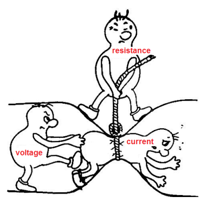
Some materials become superconductors (essentially zero resistance) at very low temperatures. The temperature below which a material becomes a superconductor is called the critical temperature $\left(T_c\right)$. For example, the critical temperature for mercury is $4.2 \mathrm{~K}$, as shown in the graph to the right.
conductivity $(\sigma)$ : the innate ability of a substance to conduct electricity. Conductivity $(\sigma)$ is the inverse of resistivity, and is measured in siemens (S). Siemens used to be called mhos (symbol $\circlearrowright$ ). 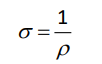
(Note that “mho” is “ohm” spelled backwards.)
ohmic resistor: a resistor whose resistance is the same regardless of voltage and current. The filament of an incandescent light bulb is an example of a nonohmic resistor, because the current heats up the filament, which increases its resistance. (This is necessary in order for the filament to also produce light.)
capacitance (C ): the ability of an object to hold an electric charge. 
Capacitance (C ) is a scalar quantity and is measured in farads (F). One farad equals one coulomb per volt.
power $(P)$ : as discussed in the mechanics section of this course, power $(P)$ is the work done per unit of time and is measured in watts (W).
In electric circuits:
$
P=\frac{W}{t}=I \Delta V=I^2 R=\frac{(\Delta V)^2}{R}
$
work $(W)$ : recall from mechanics that work $(W)$ equals power times time, and is measured in either newton-meters $(N \cdot m)$ or joules $(J)$ :
$
W=P t=I \Delta V t=I^2 R t=\frac{(\Delta V)^2 t}{R}=V q
$
Electrical work or energy is often measured in kilowatt-hours (kW·h).
$
1 \mathrm{~kW} \cdot \mathrm{h} \equiv 3.6 \times 10^6 \mathrm{~J} \equiv 3.6 \mathrm{MJ}
$
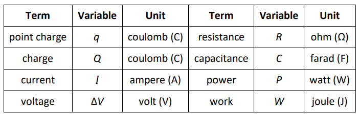
Summary of Terms, Units and Variables
Alternating Current vs. Direct Current
Electric current can move in two ways.
direct current: electric current flows through the circuit, starting at the positive terminal of the battery or power supply, and ending at the negative terminal. Batteries supply direct current. A typical AAA, AA, C, or D battery supplies 1.5 volts $D C$.
However, the net flow of charged particles through a wire is very slow. Electrons continually collide with one another in all directions as they drift slowly through the circuit. Electrons in a DC circuit have a net velocity of about one meter per hour
alternating current: electric current flows back and forth in one direction and then the other, like a sine wave. The current alternates at a particular frequency. In the U.S., household current is 110 volts AC with a frequency of 60 Hz. Alternating current requires higher voltages in order to operate devices, but has the advantage that the voltage drop is much less over a length of wire than with direct current.
Sample Problems:
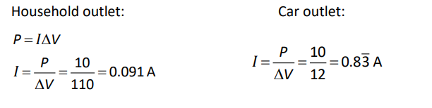
Q: A simple electrical device uses $1.5 \mathrm{~A}$ of current when plugged into a $110 \mathrm{~V}$ household electrical outlet. How much current would the same device draw if it were plugged into a $12 \mathrm{~V}$ outlet in a car?
Answer/Explanation
A: Resistance is a property of a specific object. Because we are not told otherwise, we assume the device is ohmic and the resistance is the same regardless of the current.
Therefore, our strategy is to use the information about the device plugged into a household outlet to determine the device’s resistance, then use the resistance to determine how much current it draws in the car.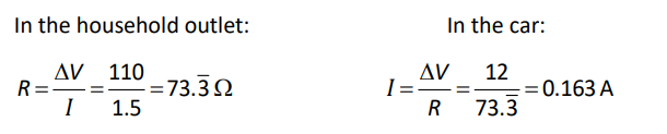
Q: A laptop computer uses $10 \mathrm{~W}$ of power. The laptop’s power supply adjusts the current so that the power is the same regardless of the voltage supplied. How much current would the computer draw from a $110 \mathrm{~V}$ household outlet? How much current would the same laptop computer need to draw from a $12 \mathrm{~V}$ car outlet?
Answer/Explanation
A: The strategy for this problem is the same as the previous one.
Electrical Components
Notes:
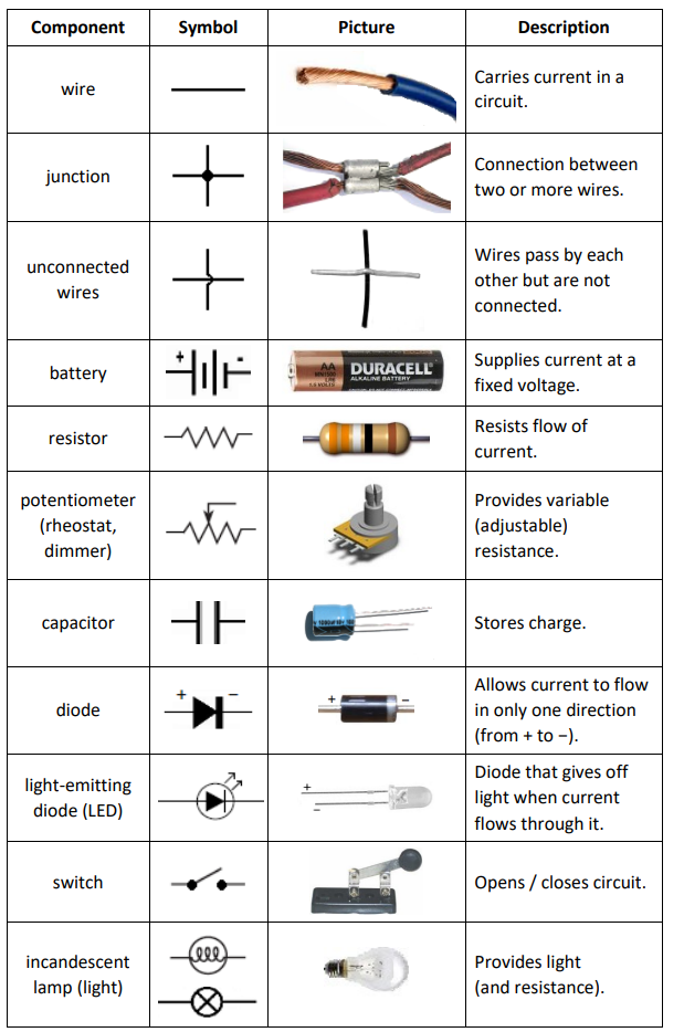
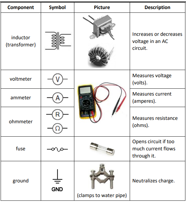
electrical component: an object that performs a specific task in an electric circuit. A circuit is a collection of components connected together so that the tasks performed by the individual components combine in some useful way.
circuit diagram: a picture that represents a circuit, with different symbols representing the different components.
The following table describes some of the common components of electrical circuits, what they do, and the symbols that are used to represent them in circuit diagrams.
EMF & Internal Resistance of a Battery
Notes:
An ideal battery always supplies current at the voltage of the electrochemical cells inside of it. In a real battery, the voltage is a little less when the battery is “under load” (supplying current to a circuit) than when it is tested with no load. This difference is caused by real-world limitations of the chemical and physical processes that occur inside of the battery.
electromotive force (emf): the potential difference (voltage) supplied by a battery without load. This is the stated voltage of the battery. The term “electromotive force” literally means “electron-moving force”. EMF is often represented by the variable $\varepsilon$.
voltage: the observed potential difference between two points in a circuit. The voltage of a battery usually means the voltage under load.
To account for internal resistance, we model a battery as if it were a power supply with the ideal voltage, plus a resistor that is physically inside of the battery.
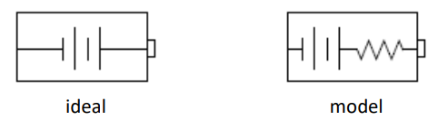
Note that this is a model; the actual situation is more complex, because in addition to the resistivity of the battery’s component materials, the difference between the internal voltage and the supplied voltage also depends on factors such as electrolyte conductivity, ion mobility, and electrode surface area.
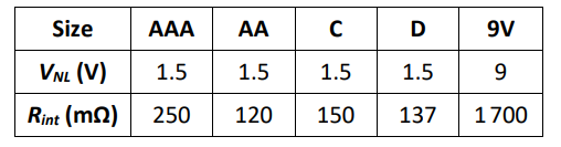
The following table shows the nominal voltage and internal resistance of common Duracell (coppertop) dry cell batteries of different sizes. These numbers are given by the manufacturer for a new battery at room temperature $\left(25^{\circ} \mathrm{C}\right)$ :
The internal resistance can be used to calculate the maximum current that a battery could theoretically supply. If you were to connect a wire from the positive terminal of a battery to the negative terminal, the only resistance in the circuit should be the battery’s internal resistance.
The theoretical maximum current that the battery can supply is therefore the current that would be supplied when the only resistance is the battery’s internal resistance, and can be calculated from Ohm’s Law:
$
I_{\max }=\frac{\Delta V}{R_{\mathrm{int}}}
$
Note also that the factors that affect a battery’s internal resistance change as the battery ages. The following graph shows the changes in voltage and internal resistance of an alkaline AA battery as it supplied a current of 50 mA.
Internal resistance can be calculated by measuring the voltage with no “load” on the battery (i.e., the voltmeter is connected directly to the battery with nothing else in the circuit) and the voltage with “load” (i.e., the battery is connected to a circuit with measurable resistance):
$
R_{\mathrm{int}}=\left(\frac{\Delta V_{N L}}{\Delta V_{F L}}-1\right) R_L
$
where:
$\begin{aligned} R_{\mathrm{int}}= & \text { internal resistance of battery } \\ \Delta V_{F L}= & \text { voltage measured with full load (resistor with resistance } R_L \text { in circuit) } \\ \Delta V_{N L}= & \text { voltage measured with no load (voltmeter connected directly to } \\ & \text { battery) } \\ R_L= & \text { resistance of the load (resistor) that is used to experimentally } \\ & \text { determine the internal resistance of the battery }\end{aligned}$
Circuits
Notes:
circuit: an arrangement of electrical components that allows electric current to pass through them so that the tasks performed by the individual components combine in some useful way.
closed circuit: a circuit that has a complete path for current to flow from the positive terminal of the battery or power supply through the components and back to the negative terminal.
open circuit: a circuit that has a gap such that current cannot flow from the positive terminal to the negative terminal.
short circuit: a circuit in which the positive terminal is connected directly to the negative terminal with no load (resistance) in between.
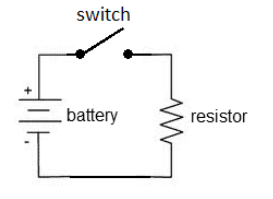
A diagram of a simple electric circuit might look like the diagram to the right.
When the switch is closed, the electric current flows from the positive terminal of the battery through the switch, through the resistor, and back to the negative terminal of the battery.
An electric circuit needs a power supply (often a battery) that provides current at a specific voltage (electric potential difference), and one or more components that use the energy provided.
The battery or power supply continues to supply current, provided that:
1. There is a path for the current to flow from the positive terminal to the negative terminal, and
2. The total resistance of the circuit is small enough to allow the current to flow.
If the circuit is broken, current cannot flow and the chemical reactions inside the battery stop.
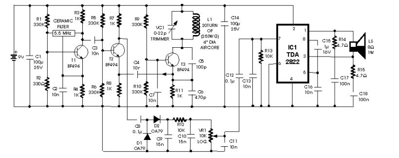
As circuits become more complex, the diagrams reflect this increasing complexity. The following is a circuit diagram for a metal detector:
Analyzing an electrical circuit means figuring out the potential difference (voltage), current, and/or resistance contributed by each component of a circuit.
Series vs. Parallel Circuits
If a circuit has multiple components, they can be arranged in series or parallel.
series: Components in series lie along the same path, one after the other.

parallel: Components in parallel lie in separate paths.
Note that complex circuits may have some components that are in series with each other and other components that are in parallel.
Sample Problem:
Q: A circuit consists of a battery, two switches, and three light bulbs. Two of the bulbs are in series with each other, and the third bulb is in parallel with the others. One of the switches turns off the two light bulbs that are in series with each other, and the other switch turns off the entire circuit. Draw a schematic diagram of the circuit, using the correct symbol for each component.
Answer/Explanation
A:
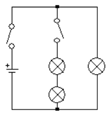
Note that no sensible person would intentionally wire a circuit this way. It would make much more sense to have the second switch on the branch with the one light bulb, so you could turn off either branch separately or both branches by opening both switches. This is an example of a strange circuit that a physics teacher would use to make sure you really can follow exactly what the question is asking!
Kirchhoff’s Rules
Notes:
In 1845 , the German physicist Gustav Kirchhoff came up with two simple rules that describe the behavior of current in complex circuits. Those rules are:
Kirchhoff’s junction rule: the total current coming into a junction must equal the total current coming out of the junction.
The junction rule is based on the concept that electric charge cannot be created or destroyed. Current is simply the flow of electric charge, so any charges that come into a junction must also come out of it.
Kirchhoff’s loop rule: the sum of the voltages around a closed loop must add up to zero.
The loop rule is based on the concept that voltage is the difference in electric potential between one location in the circuit and another. If you come back to the same point in the circuit, the difference in electric potential between where you started and where you ended (the same place) must be zero. Therefore, any increases and decreases in voltage around the loop must cancel.
Junction Rule Example:
As an example of the junction rule, consider the following circuit:
The junction rule tells us that the current flowing into junction $\mathrm{J} 1$ must equal the current flowing out. If we assume current $I_1$ flows into the junction, and currents $I_2$ and $I_3$ flow out of it, then $I_1=I_2+I_3$.
We know that the voltage across both resistors is $12 \mathrm{~V}$. From Ohm’s Law we can determine that the current through the $3 \Omega$ resistor is $I_2=4 \mathrm{~A}$, and the current through the $4 \Omega$ resistor is $I_3=3 \mathrm{~A}$. The junction rule tells us that the total current must therefore be:
$
I_1=I_2+I_3=4 \mathrm{~A}+3 \mathrm{~A}=7 \mathrm{~A}
$
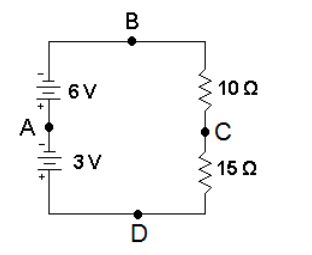
Loop Rule Example
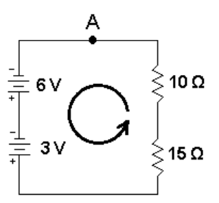
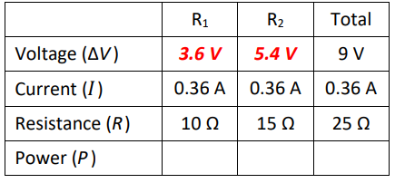
For the loop rule, consider the circuit to the right:
If we start at point A and move counterclockwise around the loop (in the direction of the arrow), the voltage should be zero when we get back to point A. For this example, we are moving around the circuit in the same direction that the current flows, because that makes the most intuitive sense. However, it wouldn’t matter if we moved clockwise instead—just as with vector quantities, we choose a positive direction and assign each quantity to a positive or negative number accordingly, and the math tells us what is actually happening.
Starting from point $\mathrm{A}$, we first move through the $6 \mathrm{~V}$ battery. We are moving from the negative pole to the positive pole of the battery, so the voltage increases by $+6 \mathrm{~V}$. When we move through the second battery, the voltage increases by $+3 \mathrm{~V}$.
Next, we move through the $15 \Omega$ resistor. When we move through a resistor in the positive direction (of current flow), the voltage drops, so we assign the resistor a voltage of $-15 I$ (based on $V=I R$, where $I$ is the current through the resistor).
Similarly, the voltage across the $10 \Omega$ resistor is $-10 \mathrm{I}$. Applying the loop rule gives:
$
\begin{aligned}
6+3+(-15 I)+(-10 I) & =0 \\
9-25 I & =0 \\
9 & =25 I \\
I & =\frac{9}{25}=0.36 \mathrm{~A}
\end{aligned}
$
Now that we know the total current, we can use it to find the voltage drop (potential difference) across the two resistors.
$
\Delta V_{10 \Omega}=I R=(0.36)(10)=3.6 \mathrm{~V} \quad \Delta V_{15 \Omega}=I R=(0.36)(15)=5.4 \mathrm{~V}
$
Sample Problem using Kirchhoff’s Rules:
Find the voltage and current across each resistor in the following circuit:
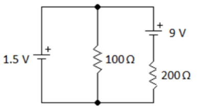
Applying the junction rule, we choose arbitrary directions for current:
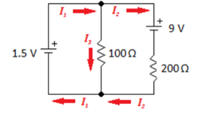
By closer inspection, we can see that the direction for $I_2$ is probably going to be wrong. This means we expect that $I_2$ will come out to a negative number.
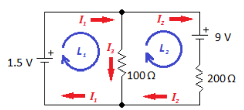
Now that we have defined the directions for current using the junction rule, we apply the loop rule. Again, we choose the direction of each loop rule. Again, we choose the direction of each loop arbitrarily, without worrying about which direction we have chosen for current. The loop direction is simply the order in which we inspect each element. The numbers will be determined by the direction we chose for current.
As we inspect our way around the loop, there are two rules for determining the voltage across each component:
1. Voltage across a battery is positive if the loop direction is from negative to positive (the “forward” direction).
Voltage across a battery is negative if the loop direction is from positive to negative (the “backward” direction).
2. Voltage across a resistor is negative if the loop direction is with the current (the resistor is “using up” voltage).
Voltage across a resistor is positive if the loop direction is against the current (we are traveling from a place where the electric potential is lower to a place where it is higher).
Now we inspect our way around each loop, writing the equations for the voltages:
$\begin{array}{ll}\mathrm{L} 1: & +1.5-100 I_3=0 \rightarrow I_3=0.015 \mathrm{~A} \\ \mathrm{~L} 2: \quad & -9-200 I_2+100 I_3=0 \\ & -9-200 I_2+1.5=0 \\ & -7.5=200 I_2 \\ & I_2=-0.0375 \mathrm{~A} \\ & I_1=I_2+I_3=-0.0375+0.015=-0.0225 \mathrm{~A}\end{array}$
$I_3$ came out to a positive number, meaning that the current is flowing in the direction that we chose initially. However, $I_1$ and $I_2$ both came out negative, meaning that the current in those two segments of the circuit is actually flowing in the opposite direction from the arbitrary direction that we chose at the beginning of the problem.
Now that we know the current and resistance, we can find the voltage drop across each resistor using Ohm’s Law.
$
\begin{array}{ll}
100 \Omega: & V=I_3 R=(0.015)(100)=1.5 \mathrm{~V} \\
200 \Omega: & V=I_2 R=(-0.0375)(200)=-7.5 \mathrm{~V}
\end{array}
$
Again, the negative sign shows that the voltage drop (from positive to negative) is in the opposite direction from what we originally chose.
Series Circuits (Resistance Only)
Notes:
series: Components in series lie along the same path, one after the other.
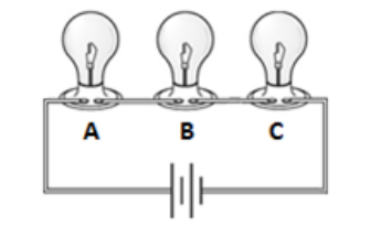
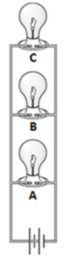
In a series circuit, all of the current flows through every component, one after another. If the current is interrupted anywhere in the circuit, no current will flow. For example, in the following series circuit, if any of the light bulbs A, B, or C is removed, no current can flow and none of the light bulbs will be illuminated.
Because some of the electric potential energy (voltage) is “used up” by each bulb in the circuit, each additional bulb means the voltage is divided among more bulbs and is therefore less for each bulb. This is why light bulbs get dimmer as you add more bulbs in series.
Christmas tree lights used to be wired in series. This caused a lot of frustration, because if one bulb burned out, the entire string went out, and it could take several tries to find which bulb was burned out.
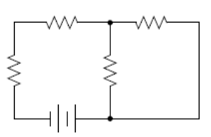
The diagram to the right shows two batteries and two resistors in series.
Current
Because there is only one path, all of the current flows through every component. This means the current is the same through every component in the circuit:
$
I_{\text {total }}=I_1=I_2=I_3=\ldots
$
Voltage
In a series circuit, if there are multiple voltage sources (e.g., batteries), the voltages add:
$
\Delta V_{\text {total }}=\Delta V_1+\Delta V_2+\Delta V_3+\ldots
$
In the above circuit, there are two batteries, one that supplies $6 \mathrm{~V}$ and one that supplies $3 V$. The voltage from $A$ to $B$ is $+6 V$, the voltage from $A$ to $D$ is $-3 V$ (note that $A$ to $D$ means measuring from negative to positive), and the voltage from $D$ to $B$ is $(+3 V)+(+6 V)=+9 V$.
Resistance
If there are multiple resistors, each one contributes to the total resistance and the resistances add:
$
R_{\text {total }}=R_1+R_2+R_3+\ldots
$
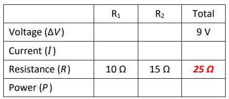
In the above circuit, the resistance between points $B$ and $D$ is $10 \Omega+15 \Omega=25 \Omega$.
Power
In all circuits (series and parallel), any component that has resistance dissipates power whenever current passes through it. The total power consumed by the circuit is the sum of the power dissipated by each component:
$
P_{\text {total }}=P_1+P_2+P_3+\ldots
$
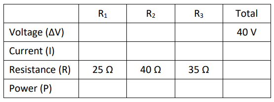
Calculations
You can calculate the voltage, current, resistance, and power of each component separately, any subset of the circuit, or entire circuit, using the equations:
$
\Delta V=I R \quad P=I \Delta V=I^2 R=\frac{(\Delta V)^2}{R}
$
“Solving” the circuit for these quantities is much like solving a Sudoku puzzle. You systematically decide which variables (for each component and/or the entire circuit) you have enough information to solve for. Each result enables you to determine more and more of the, until you have found all of the quantities you need.
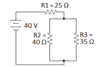
Sample Problem:
Suppose we are given the following series circuit:
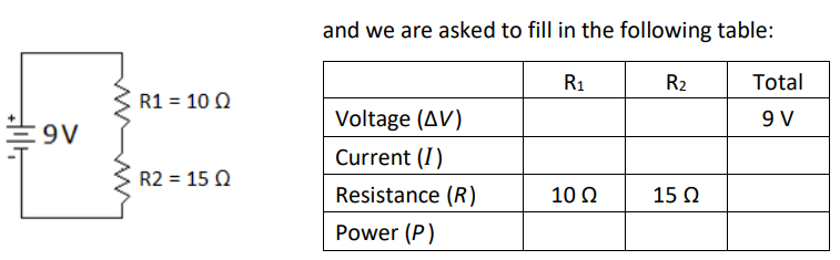
First, we recognize that resistances in series add, which gives us:
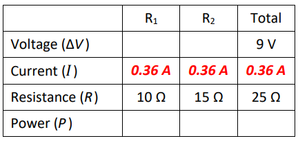
Now, we know two variables in the “Total” column, so we use ΔV = IR to find the current.
$\begin{aligned} & \Delta V=I R \\ & 9=(I)(25) \\ & I=\frac{9}{25}=0.36 \mathrm{~A}\end{aligned}$
Because this is a series circuit, the total current is also the current through $R_1$ and $R_2$.
As soon as we know the current, we can find the voltage across $R_1$ and $R_2$, again using $\Delta V=I R$.
Finally, we can fill in the power, using P = I ΔV:
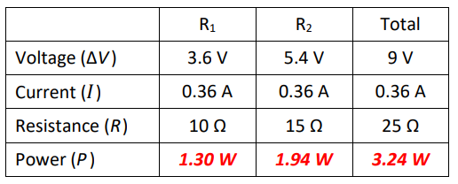
Parallel Circuits (Resistance Only)
parallel: Components in parallel lie in separate paths
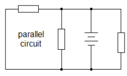
In a parallel circuit, the current divides at each junction, with some of the current flowing through each path. If the current is interrupted in one path, current can still flow through the other paths. For example, in the parallel circuit to the right, if any of light bulbs $A, B$, or $C$ is removed, current still flows through the remaining bulbs.
Because the voltage across each branch is equal to the total voltage, all of the bulbs will light up with full brightness, regardless of how many bulbs are in the circuit. (However, each separate light bulb draws the same amount of current as if it were the only thing in the circuit, so the total current in the circuit increases with each new branch. This is why you trip a circuit breaker or blow a fuse if you have too many high-power components plugged into the same circuit.)
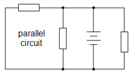
The following circuit shows a battery and three resistors in parallel:
Current
The current divides at each junction (as indicated by the arrows). This means the current through each path must add up to the total current:
$
I_{\text {total }}=I_1+I_2+I_3+\ldots
$
Voltage
In a parallel circuit, the potential difference (voltage) across the battery is always the same ( $12 \mathrm{~V}$ in the above example). Therefore, the potential difference between any point on the top wire and any point on the bottom wire must be the same. This means the voltage is the same across each path:
$
V_{\text {total }}=V_1=V_2=V_3=\ldots
$
Resistance
If there are multiple resistors, the effective resistance of each path becomes less as there are more paths for the current to flow through. The total resistance is given by the formula:
$
\frac{1}{R_{\text {total }}}=\frac{1}{R_1}+\frac{1}{R_2}+\frac{1}{R_3}+\ldots
$
Some students find it confusing that the combined resistance of a group of resistors in series is always less than any single resistor by itself.
Power
Just as with series circuits, in a parallel circuit, any component that has resistance dissipates power whenever current passes through it. The total power consumed by the circuit is the sum of the power dissipated by each component:
$
P_{\text {total }}=P_1+P_2+P_3+\ldots
$
Electric current is analogous to water in a pipe:

• The current corresponds to the flow rate.
• The voltage corresponds to the pressure between one side and the other.
• The resistance would correspond to how small the pipe is (i.e., how hard it is to push water through the pipes). A smaller pipe has more resistance; a larger pipe will let water flow through more easily than a smaller pipe.
The voltage (pressure) drop is the same between one side and the other because less water flows through the smaller pipes and more water flows through the larger ones until the pressure is completely balanced. The same is true for electrons in a parallel circuit.
The water will flow through the set of pipes more easily than it would through any one pipe by itself. The same is true for resistors. As you add more resistors, you add more pathways for the current, which means less total resistance.
Another common analogy is to compare resistors with toll booths on a highway.
One toll booth slows cars down while the drivers pay the toll.
Multiple toll booths in a row would slows traffic down more. This is analogous to resistors in series.
Multiple toll booths next to each other (in parallel) make traffic flow faster because there are more paths for the cars to follow. Each toll booth further reduces the resistance to the flow of traffic.
Calculations
Just as with series circuits, you can calculate the voltage, current, resistance, and power of each component and the entire circuit using the equations:
$
\Delta V=I R \quad P=I \Delta V=I^2 R=\frac{(\Delta V)^2}{R}
$
Sample Problem
Suppose we are given the following parallel circuit:
Because this is a parallel circuit, the total voltage equals the voltage across all three branches, so we can fill in $12 \mathrm{~V}$ for each resistor.
The next thing we can do is use $\Delta V=I R$ to find the current through each resistor:
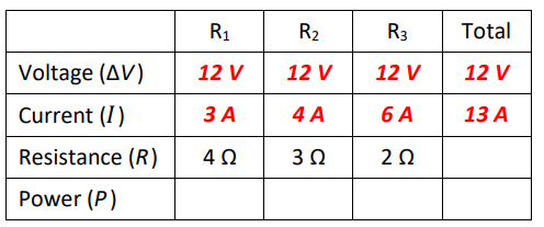
In a parallel circuit, the current adds, so the total current is $3+4+6=13 \mathrm{~A}$.
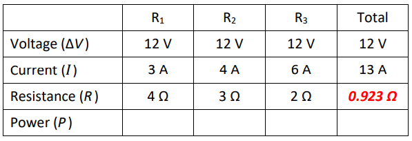
Now, we have two ways of finding the total resistance. We can use $\Delta V=I R$ with the total voltage and current, or we can use the formula for resistances in parallel:
$\begin{array}{clr} & \frac{1}{R_{\text {total }}}=\frac{1}{R_1}+\frac{1}{R_2}+\frac{1}{R_3} \\ \Delta V=I R & \frac{1}{R_{\text {total }}}=\frac{1}{4}+\frac{1}{3}+\frac{1}{2} \\ 12=13 R & \frac{1}{R_{\text {total }}}=\frac{3}{12}+\frac{4}{12}+\frac{6}{12}=\frac{13}{12} \\ R=\frac{12}{13}=0.923 \Omega & R_{\text {total }}=\frac{12}{13}=0.923 \Omega\end{array}$
Now we have:
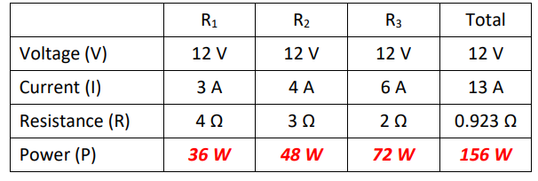
As we did with series circuits, we can calculate the power, using P = I ΔV:
Batteries in Parallel
One question that has not been answered yet is what happens when batteries are connected in parallel.
If the batteries have the same voltage, the potential difference (voltage) remains the same, but the total current is the combined current from the two batteries.
However, if the batteries have different voltages there is a problem, because each battery attempts to maintain a constant potential difference (voltage) between its terminals. This results in the higher voltage battery overcharging the lower voltage battery.
Remember that physically, batteries are electrochemical cells-small solid-state chemical reactors with redox reactions taking place in each cell. If one battery overcharges the other, material is deposited on the cathode (positive terminal) until the cathode becomes physically too large for its compartment, at which point the battery bursts and the chemicals leak out.
Light Bulbs
Electric light bulbs, which were invented by Thomas Edison in 1880 , use electrical energy to produce light. For about 100 years, most light bulbs were incandescent bulbs, pass electricity through a tungsten filament until it glows white-hot.
Newer light bulbs, such as compact fluorescent (CF) bulbs or lightemitting diode (LED) bulbs, produce similar amounts of light but much less heat, making them much more energy efficient.
The S.I. unit for light intensity is the lumen (Im).
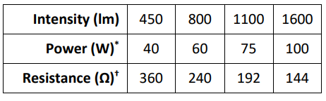
The amount of light that a light bulb produces is proportional to the amount of power it consumes. For over 100 years, incandescent bulbs were sold according to their power rating (in watts), and people developed an understanding of how much light a typical incandescent bulb would produce in a $120 \mathrm{~V}$ household circuit. Note that the power consumed by a light bulb is a function of both the current and the voltage: $P=I \Delta V$.
- In a parallel circuit (such as you would find in your house), the voltage is constant. The resistance of a component determines how much current it draws. A component with lower resistance (e.g., a light bulb with a higher “wattage” rating) draws more current, and therefore uses more power. This means a bulb with a higher “wattage” rating will be brighter in a parallel circuit.
- In a series circuit, the current through each bulb is constant (because there is only one path). The voltage across the entire circuit is fixed, but the voltage across each component splits according to the component’s resistance. A component with less resistance (e.g., a light bulb with a higher “wattage” rating) “uses up” less of the total voltage and therefore uses less power. This means a bulb with a higher “wattage” rating will be dimmer in a series circuit.
” For an incandescent bulb, assuming a $120 \mathrm{~V}$ household circuit.
† For an incandescent bulb. Note that light bulbs are not ohmic resistors, meaning their resistance changes as the current changes. These values are for bulbs in a $120 \mathrm{~V}$ household circuit.
Mixed Series & Parallel Circuits (Resistance Only)
Notes:
If a circuit has mixed series and parallel sections, you can determine the various voltages, currents and resistances by applying Kirchhoff’s Rules and/or by “simplifying the circuit.” Simplifying the circuit, in this case, means replacing groups of resistors that are in series or parallel with a single resistor of equivalent resistance
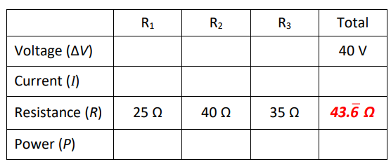
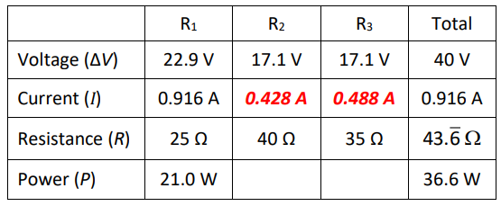
For example, suppose we need to solve the following mixed series & parallel circuit for voltage, current, resistance and power for each resistor:
Because the circuit has series and parallel sections, we cannot simply use the series and parallel rules across the entire table.
We can use Ohm’s Law $(\Delta V=I R)$ and the power equation $(P=I \Delta V)$ on each individual resistor and the totals for the circuit (columns), but we need two pieces of information for each resistor in order to do this.
Our strategy will be:
1. Simplify the resistor network until all resistances are combined into one equivalent resistor to find the total resistance.
2. Use $\Delta V=I R$ to find the total current.
3. Work backwards through your simplification, using the equations for series and parallel circuits in the appropriate sections of the circuit until you have all of the information.
Step 1: If we follow the current through the circuit, we see that it goes through resistor R1 first. Then it splits into two parallel pathways. One path goes through R2 and R3, and the other goes through R4 and R5.
There is no universal shorthand for representing series and parallel components, so let’s define the symbols “- “to show resistors in series, and “II” to show resistors in parallel. The above network of resistors could be represented as:
$
R 1-(R 2 \| R 3)
$
Now, we simplify the network just like a math problem-start with the innermost parentheses and work your way out.
Step 2: Combine the parallel $40 \Omega$ and $35 \Omega$ resistors into a single equivalent resistance:
$
\begin{gathered}
25 \Omega-(40 \Omega \| 35 \Omega) \rightarrow 25 \Omega-\left(R_{\text {eq..II }}\right) \\
\frac{1}{R_{\text {total }}}=\frac{1}{40}+\frac{1}{35} \\
\frac{1}{R_{\text {total }}}=0.0250+0.0286=0.0536 \\
R_{\text {total }}=\frac{1}{0.0536}=18 . \overline{6} \Omega
\end{gathered}
$
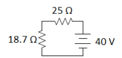
Now our circuit is equivalent to:
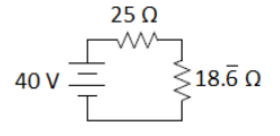
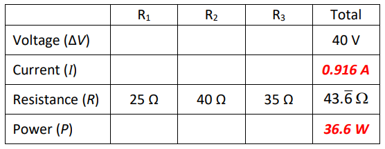
Step 3: Add the two resistances in series to get the total combined resistance of the circuit:
$\begin{gathered}25 \Omega-18 . \overline{6} \Omega \longrightarrow R_{\text {total }} \\ 18 . \overline{6}+25=43 . \overline{6} \Omega\end{gathered}$
This gives:
Step 4: Now that we know the total voltage and resistance, we can use Ohm’s Law to find the total current:
$
\begin{aligned}
\Delta V & =I R \\
40 & =I(43 . \overline{6}) \\
I & =\frac{40}{43 . \overline{6}}=0.916 \mathrm{~A}
\end{aligned}
$
While we’re at it, let’s use $P=I \Delta V=(0.916)(40)=36.6 \mathrm{~W}$ to find the total power.
Now we work backwards.
The next-to-last simplification step was:
The $25 \Omega$ resistor is R1. All of the current goes through it, so the current through R1 must be 0.916 A. Using Ohm’s Law, this means the voltage drop across R1 must be:
$
\Delta V=I R=(0.916)(25)=22.9 \mathrm{~V}
$
and the power must be:
$
P=I \Delta V=(0.916)(22.9)=21.0 \mathrm{~W}
$
This means that the voltage across the parallel portion of the circuit (R2 \|R R3) must be $40-22.9=17.1 \mathrm{~V}$. Therefore, the voltage is $17.1 \mathrm{~V}$ across both parallel branches (because voltage is the same across parallel branches).
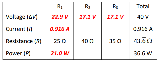
We can use this and Ohm’s Law to find the current through one branch:
$\begin{gathered}\Delta V_{40 \Omega}=\Delta V_{35 \Omega}=40-\Delta V_1=40-22.9=17.1 \mathrm{~V} \\ \Delta V_{40 \Omega}=I_{40 \Omega} R_{40 \Omega} \\ I_{40 \Omega}=\frac{\Delta V_{40 \Omega}}{R_{40 \Omega}}=\frac{17.1}{40}=0.428 \mathrm{~A}\end{gathered}$
We can use Kirchhoff’s Junction Rule to find the current through the other branch:
$
\begin{aligned}
I_{\text {total }} & =I_{40 \Omega}+I_{35 \Omega} \\
0.916 & =0.428+I_{35 \Omega} \\
I_{35 \Omega} & =0.488 \mathrm{~A}
\end{aligned}
$
This gives us:
Finally, because we now have current and resistance for each of the resistors $R_2$ and $R_3$, we can use $P=I \Delta V$ to find the power:
$
\begin{aligned}
& P_2=I_2 \Delta V_2=(0.428)(17.1)=7.32 \mathrm{~W} \\
& P_3=I_3 \Delta V_3=(0.488)(17.1)=8.34 \mathrm{~W}
\end{aligned}
$
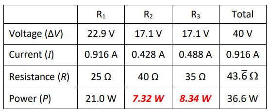
Alternately, because the total power is the sum of the power of each component, once we had the power in all but one resistor, we could have subtracted from the total to find the last one.
Measuring Voltage, Current & Resistance
Notes:
Analyzing an electrical circuit means figuring out the potential difference (voltage), current, and/or resistance in each component of a circuit. In order to analyze actual circuits, it is necessary to be able to measure these quantities.
Measuring Voltage
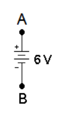
Suppose we want to measure the electric potential (voltage) across the terminals of a $6 \mathrm{~V}$ battery. The diagram would look like this:
The voltage between points $A$ and $B$ is either $+6 V$ or $-6 V$, depending on the direction. The voltage from $A$ to $B$ (positive to negative) is $+6 \mathrm{~V}$, and the voltage from $\mathrm{B}$ to $\mathrm{A}$ (negative to positive) is $-6 \mathrm{~V}$.
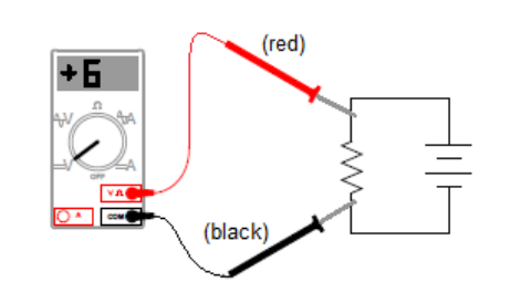
To measure voltage:
1. The circuit needs to be powered up with current flowing through it.
2. Make sure the red lead is plugged into the $\mathrm{V} \Omega$ socket (for measuring volts or ohms).
3. Make sure that the voltmeter is set for volts (DC or $A C$, as appropriate).
4. Touch the two leads in parallel with the two points you want to measure the voltage across. (Remember that voltage is the same across all branches of a parallel circuit. You want the voltmeter to be one of the branches, and the circuit to be the other branch with the same voltage.)
On a voltmeter (a meter that measures volts or voltage), positive voltage means the current is going from the red (+) lead to the black (-) lead. In the following circuit, if you put the red (+) lead on the end of a resistor that is closer to the positive terminal of the battery, and the black (-) lead on the end that is closer to the negative terminal, the voltage reading will be positive. In this circuit, the voltmeter reads $+6 \mathrm{~V}:$
However, if you reverse the leads so that the black $(-)$ lead is closer to the positive terminal and the red (+) lead is closer to the negative terminal, the voltage reading will be negative. In this circuit, the voltmeter reads $-6 \mathrm{~V}$ :
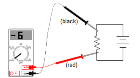
The reading of $-6 \mathrm{~V}$ indicates that the current is actually flowing in the opposite direction from the way the voltmeter is measuring -from the black $(-)$ lead to the red (+) lead.
Measuring Current
To measure current:
1. The circuit needs to be open between the two points where you want to measure the current.
2. Make sure the red lead is plugged into appropriate socket $(10 \mathrm{~A}$ if the current is expected to be $0.5 \mathrm{~A}$ or greater; $1 \mathrm{~A}$ or $\mathrm{mA} / \mu \mathrm{A}$ if the current is expected to be less than $0.5 \mathrm{~A})$.
3. Make sure the ammeter is set for amperes $(A)$, milliamperes $(\mathrm{mA})$ or microamperes $(\mu \mathrm{A}) \mathrm{AC}$ or $D C$, depending on what you expect the current in the circuit to be.
4. Touch one lead to each of the two contact points, so that the ammeter is in series with the rest of the circuit. (Remember that current is the same through all components in a series circuit. You want to measure all of the current, so you want all of the current to flow through the meter.)
On an ammeter (a meter that measures current), the current is measured assuming that it is flowing from the red (+) lead to the black (-) lead. In the following circuit, if you put the red (+) lead on the side that is connected to the positive terminal and the black (-) lead on the end that is connected to the negative terminal, the current reading would be positive. In this circuit, the current is $+3 \mathrm{~A}$ :
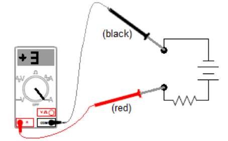
As with the voltage example above, if you switched the leads, the reading would be −3A instead of +3A.
Measuring Resistance
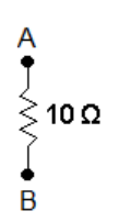
Resistance does not have a direction. If you placed an ohmmeter (a meter that measures resistance) across points A and B, it would read 10Ω regardless of which lead is on which point.
An ohmmeter supplies a voltage across the component and measures the current. Because the voltage supplied is constant, the Ohm’s Law calculation is built into the meter and the readout displays the resistance. To measure resistance:
1. The circuit needs to be open. Because the meter is applying a voltage and measuring current, you do not want other voltages or currents in the circuit.
2. Make sure the red lead is plugged into the VΩ socket (for measuring volts or ohms).
3. Make sure that the voltmeter is set for Ω.
4. Touch one lead to each end of the resistor.
It is sometimes easier and/or more reliable to measure the voltage and current and calculate resistance using Ohm’s Law (V = IR).
Capacitance
Notes:
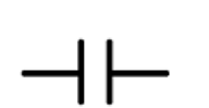
capacitor: an electrical component that stores electrical charge but does not allow current to flow through.
When a voltage is applied to the circuit, one side of the capacitor will acquire a positive charge, and the other side will acquire an equal negative charge. This process is called charging the capacitor.
When a charged capacitor is placed in a circuit (perhaps it was charged previously, and then the voltage source is switched off), charge flows out of the capacitor into the circuit. This process is called discharging the capacitor.
No current actually flows through the capacitor, but as it charges, the positive charges that accumulate on one side of the capacitor repel positive charges from the other side into the rest of the circuit. This means that an uncharged capacitor acts like a wire when it first begins to charge.
Once the capacitor is fully charged, the amount of potential difference in the circuit is unable to add any more charge, and no more charges flow. This means that $a$ fully-charged capacitor in a circuit that has a power supply (e.g., a battery) it acts like an open switch or a broken wire.
If you disconnect the battery and reconnect the capacitor to a circuit that allows the capacitor to discharge, charges will flow out of the capacitor and through the circuit. This means that a fully-charged capacitor in a circuit without a separate power supply acts like a battery when it first begins to discharge.
Toys from joke shops that shock people use simple battery-and-capacitor circuits. The battery charges the capacitor gradually over time until a significant amount of charge has built up. When the person grabs the object, the person completes a circuit that discharges the capacitor, resulting in a sudden, unpleasant electric shock.
The simplest capacitor (conceptually) is a pair of parallel metal plates separated by a fixed distance. The symbol for a capacitor is a representation of the two parallel plates.
The first capacitors were made independently in 1745 by the German cleric Ewald Georg von Kleist and by the Dutch scientist Pieter van Musschenbroek. Both von Kleist and van Musschenbroek lined a glass jar with metal foil on the outside and filled the jar with water. (Recall that water with ions dissolved in it conducts electricity.) Both scientists charged the device with electricity and received a severe shock when they accidentally discharged the jars through themselves.
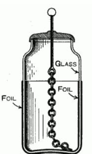
This type of capacitor is named after is called a Leyden jar, after the city of Leiden (Leyden) where van Musschenbroek lived.
Modern Leyden jars are lined on the inside and outside with conductive metal foil. As a potential difference is applied between the inside and outside of the jar, charge builds up between them. The glass, which acts as an insulator (a substance that does not conduct electricity), keeps the two pieces of foil separated and does not allow the charge to flow through. Because the thickness of the jar is more or less constant, the Leyden jar behaves like a parallel plate capacitor.
Shortly after the invention of the Leyden jar, Daniel Gralath discovered that he could connect several jars in parallel to increase the total possible stored charge.
Benjamin Franklin compared this idea with a “battery” of cannon. (The original meaning of the term “battery” was a collection of cannon for the purpose of battering the enemy.) The term is now used to describe a similar arrangement of electrochemical cells.
Franklin’s most famous experiment was to capture the charge from a lightning strike in Leyden jars, proving that lightning is an electric discharge.
capacitance: a measure of the ability of a capacitor to store charge. Capacitance is measured in farads (F), named after the English physicist Michael Faraday.
Capacitance is the ratio of the charge stored by a capacitor to the voltage applied:
$C=\frac{Q}{\Delta V} \quad$ which is often represented as $\quad Q=C \Delta V$
Thus one farad is one coulomb per volt. Note, however, that one farad is a ridiculously large amount of capacitance. The capacitors in most electrical circuits are in the millifarad $(\mathrm{mF})$ to picofarad $(\mathrm{pF})$ range.
Capacitance is the theoretical limit of the charge that a capacitor could store at a given potential difference (voltage) if the charge were allowed to build up over an infinite amount of time.
As a capacitor is charged, the positive side increasingly repels additional positive charges coming from the voltage source, and the negative side increasingly repels additional negative charges. This means that the capacitor charges rapidly at first, but the amount of charge stored decreases exponentially as the charge builds up.
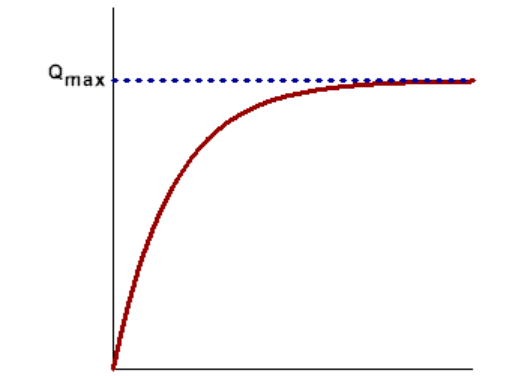
Note that $Q_{\max }$ is sometimes labeled $Q_0$. Be careful-in this case, the subscript 0 does not necessarily mean at time $=0$.
Energy Stored in a Capacitor
Recall that energy is the ability to do work, and that $W=\Delta U$. Because $W=q V$, if we keep the voltage constant and add charge to the capacitor:
$
W=\Delta U=\Delta V \Delta q
$
Applying calculus* gives:
$
d U=\Delta V d q \quad \text { and therefore } \quad U=\int_0^Q \Delta V d q=\int_0^Q \frac{q}{C} d q=\frac{1}{2} \frac{Q^2}{C}
$
Because $Q=C \Delta V$, we can substitute $C \Delta V$ for $Q$, giving the equation for the stored (potential) energy in a capacitor:
$
U_C=\frac{Q^2}{2 C}=\frac{1}{2} Q V=\frac{1}{2} C V^2
$
Capacitors in Series and Parallel Circuits
Notes:
Capacitors in Parallel
When capacitors are connected in parallel:
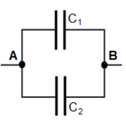
The voltage between point $\mathbf{A}$ and point $\mathbf{B}$ must be $\Delta V=V_A-V_B$, regardless of the path.
The charge on capacitor $C_1$ must be $Q_1=C_1 \Delta V$, and the charge on capacitor $C_2$ must be $Q_2=C_2 \Delta V$.
The total charge must be:
$
Q_1+Q_2=C_1 \Delta V+C_2 \Delta V=\left(C_1+C_2\right) \Delta V
$
Therefore: $
C_{e q}=\frac{Q_{\text {total }}}{\Delta V}=\frac{Q_1+Q_2}{\Delta V}=C_1+C_2
$
Generalizing this relationship, when capacitors are arranged in parallel, the total capacitance is the sum of the capacitances of the individual capacitors:
$C_{e q}=C_1+C_2+C_3+\cdots$
Capacitors in Series
In a series circuit, the voltage from one end to the other is divided among the components
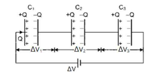
Note that the segment of the circuit that goes from the right side of $C_1$ to the left side of $C_2$ is isolated from the rest of the circuit. Current does not flow through a capacitor, which means charges cannot enter or leave this segment. Because charge is conserved (electrical charges cannot be created or destroyed), this means the negative charge on $C_1$ (which is $-Q_1$ ) must equal the positive charge on $C_2$ (which is $\left.+Q_2\right)$
By applying this same argument across each of the capacitors, all of the charges across capacitors in series must be equal to each other and equal to the total charge in that branch of the circuit. (Note that this is true regardless of whether $C_1, C_2$ and $C_3$ have the same capacitance.)
Therefore: $Q=Q_1=Q_2=Q_3$
Because the components are in series, we also know that $\Delta V=\Delta V_1+\Delta V_2+\Delta V_3$
Because $\Delta V=\frac{Q}{C}$
$
\Delta V=\frac{Q_1}{C_1}+\frac{Q_2}{C_2}+\frac{Q_3}{C_3}
$
Because $Q=Q_1=Q_2=Q_3$ :
$
\begin{gathered}
\Delta V=\frac{Q}{C_1}+\frac{Q}{C_2}+\frac{Q}{C_3}=Q\left(\frac{1}{C_1}+\frac{1}{C_2}+\frac{1}{C_3}\right) \\
\frac{\Delta V}{Q}=\frac{1}{C_{e q}}=\frac{1}{C_1}+\frac{1}{C_2}+\frac{1}{C_3}
\end{gathered}
$
Generalizing this relationship, when capacitors are arranged in series, the total capacitance is the sum of the capacitances of the individual capacitors:
$\frac{1}{C_{e q}}=\frac{1}{C_1}+\frac{1}{C_2}+\frac{1}{C_3}+\cdots$
Mixed Series and Parallel Circuits
As with resistor networks, mixed circuits involving capacitors in series and in parallel can be simplified by replacing each set of capacitors with an equivalent capacitance, starting with the innermost set of capacitors and working outwards (much like simplifying an equation by starting with the innermost parentheses and working outwards).
Sample Problem:
Simplify the following circuit:
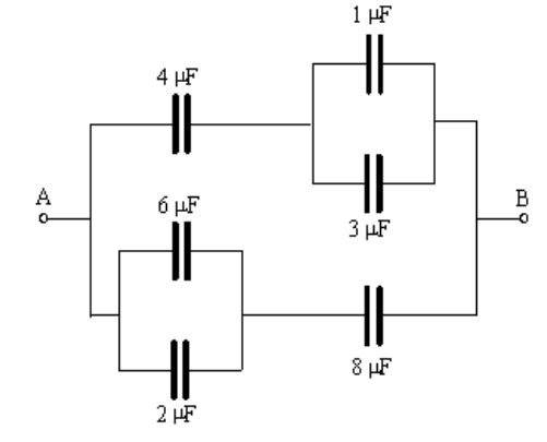
First we would add the capacitances in parallel. On top, $3 \mu \mathrm{F}+1 \mu \mathrm{F}=4 \mu \mathrm{F}$. On the bottom, $6 \mu \mathrm{F}+2 \mu \mathrm{F}=8 \mu \mathrm{F}$. This gives the following equivalent circuit:
Next, we combine the capacitors in series on top:
$
\begin{gathered}
\frac{1}{C_{e q}}=\frac{1}{C_1}+\frac{1}{C_2}=\frac{1}{4}+\frac{1}{4}=\frac{2}{4}=\frac{1}{2} \\
\frac{1}{C_{e q}}=\frac{1}{2} ; \quad \therefore C_{e q}=2 \mu \mathrm{F}
\end{gathered}
$
and the capacitors in series on the bottom:
$
\begin{gathered}
\frac{1}{C_{e q}}=\frac{1}{C_1}+\frac{1}{C_2}=\frac{1}{8}+\frac{1}{8}=\frac{2}{8}=\frac{1}{4} \\
\frac{1}{C_{e q}}=\frac{1}{4} ; \quad \therefore C_{e q}=4 \mu \mathrm{F}
\end{gathered}
$
This gives the following equivalent circuit:
Finally, we combine the last two capacitances in parallel, which gives:
$
C_{e q}=C_1+C_2=2+4=6 \mu \mathrm{F}
$
Sample Problem
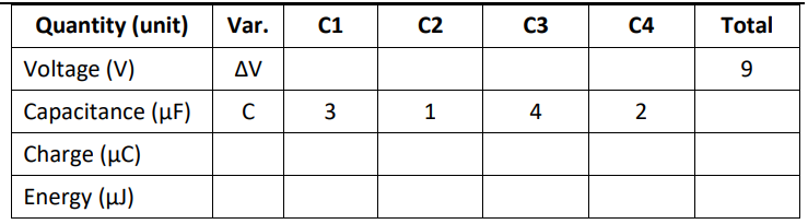
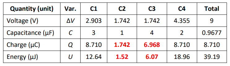
Q: Fill in the table for the following circuit:
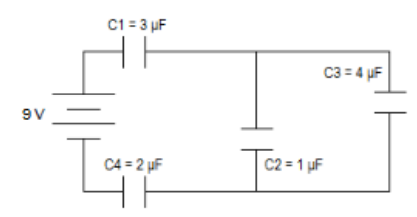
Answer/Explanation
A: Let’s start by combining the two capacitors in parallel (C2 \& C3) to make an equivalent capacitor.
$
C_*=C_2+C_3=1 \mu \mathrm{F}+4 \mu \mathrm{F}=5 \mu \mathrm{F}
$
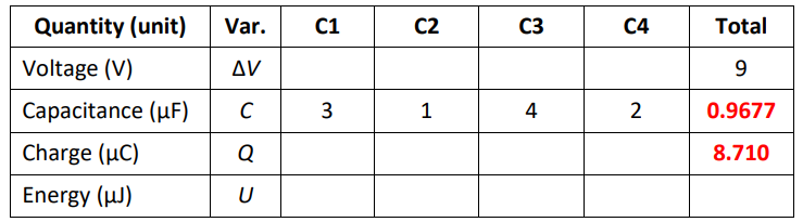
Now we have three capacitors in series: $C_1, C_*$, and $C_4$ :
$
\begin{aligned}
& \frac{1}{C_{\text {total }}}=\frac{1}{C_1}+\frac{1}{C_*}+\frac{1}{C_4}=\frac{1}{3}+\frac{1}{5}+\frac{1}{2}=0 . \overline{3}+0.2+0.5=1.0 \overline{3} \\
& C_{\text {total }}=\frac{1}{1.0 \overline{3}}=0.9677 \mu \mathrm{F} \\
&
\end{aligned}
$
Now we can calculate $Q$ for the total circuit from $Q=C \Delta V$ :
$
Q=C \Delta V=(9)(0.9677)=8.710 \mu C
$
Now we have:
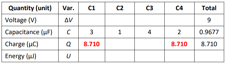
Next, because the charge is equal across all capacitors in series, we know that $Q_1=Q_*=Q_4=Q_{\text {total }}$, which gives:
Now we can calculate $\mathrm{V}_1$ and $\mathrm{V}_4$ from $Q=C \Delta V$.
We can also calculate the energy from $U_C=\frac{1}{2} Q \Delta V=\frac{1}{2} C(\Delta V)^2$
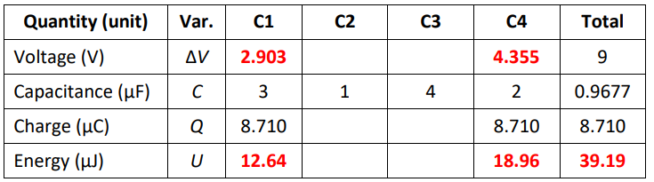
We know that voltages in series add, so $\Delta V_{\text {total }}=\Delta V_1+\Delta V_*+\Delta V_4$, which means $9=2.903+\Delta V_*+4.355$, which gives $\Delta V_*=1.742 \mathrm{~V}$
Because $C_2$ and $C_3$ (and therefore $\Delta V_2$ and $\Delta V_3$ ) are in parallel,
$
\Delta V_*=\Delta V_2=\Delta V_3=1.742 \mathrm{~V}:
$
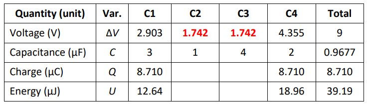
Finally, we can calculate $Q$ from $Q=C \Delta V$ and $U$ from $U_C=\frac{1}{2} Q \Delta V=\frac{1}{2} C(\Delta V)^2$ :
DC Resistor-Capacitor (RC) Circuits
Notes:
RC circuit: a circuit involving combinations of resistors and capacitors.
In an RC circuit, the amount and direction of current change with time as the capacitor charges or discharges. The amount of time it takes for the capacitor to charge or discharge is determined by the combination of the capacitance and resistance in the circuit. This makes $\mathrm{RC}$ circuits useful for intermittent (i.e., with a built-in delay) back-and-forth switching. Some common uses of RC circuits include:
- clocks
- windshield wipers
- pacemakers
- synthesizers
When we studied resistor-only circuits, the circuits were steady-state, i.e., voltage and current remained constant. RC circuits are time-variant, i.e., the voltage, current, and charge stored in the capacitor(s) are all changing with time.
Charging a Capacitor
Recall that a capacitor is an electrical component that stores charge. No current actually flows through the capacitor. Recall also that capacitance $(C)$ is a capacitor’s ability to be charged by a given electric potential difference (voltage). Therefore, the maximum charge that a capacitor can hold is:
$
Q_{\max }=C \Delta V
$
In the previous section, the charge that we calculated was actually this maximum charge $Q_{\max }$, which is the amount of charge that the capacitor would hold if it had been charged for “a long time” such that it was fully charged.
However, recall also that:
- In a capacitor with zero charge, every charge placed on one side causes an equivalent charge on the opposite side. This means: With respect to current, a capacitor with zero charge initially behaves like a wire.
- When a capacitor is fully charged, no additional charge can be added (unless the voltage is increased). This means: With respect to current, a fully-charged capacitor behaves like an open circuit.
This means that the behavior of the capacitor changes as the charges build up inside of it.
When a capacitor that initially has zero charge is connected to a voltage source, the current that flows through the circuit decreases exponentially, and the charge stored in the capacitor asymptotically approaches $Q_{\max }$, the maximum charge that can be stored in that capacitor for the voltage applied.
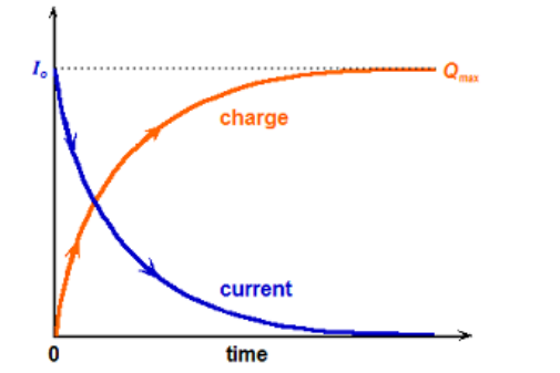
(Note that the graphs are not to scale; the y-axis scale and units are necessarily different for charge and current.)
The equations for the charge in a capacitor and the current that flows “through” it as a function of time while a capacitor is charging are:
$\begin{aligned} & I=I_o e^{-t / R c}=\frac{\Delta V}{R} e^{-t / R c} \\ & Q=Q_{\text {max }}\left(1-e^{-t / R c}\right)=C \Delta V\left(1-e^{-t / R c}\right)\end{aligned}$
where:
$\begin{aligned} I= & \text { current }(\mathrm{A}) \\ I_o= & \text { initial current (just after switch was closed) }(\mathrm{A}) \\ \Delta V= & \text { voltage }(\mathrm{V}) \\ Q= & \text { charge }(\mathrm{C}) \\ Q_{\max }= & \text { (theoretical) maximum charge stored by capacitor at the circuit’s } \\ & \text { voltage }(\mathrm{C}) \\ e= & \text { base of exponential function }=2.71828 \ldots \\ t= & \text { time since switch was closed }(\mathrm{s}) \\ R= & \text { resistance }(\Omega) \\ C= & \text { capacitance }(\mathrm{F})\end{aligned}$
We can rearrange the above equations to give:
$
\frac{I}{I_o}=1-\frac{Q}{Q_{\max }}=e^{-t / R C}
$
The $R C$ term in the exponent is known as the time constant $(\tau)$ for the circuit. Larger values of $R C$ mean the circuit takes longer to charge the capacitor. The following table shows the rate of decrease in current in the charging circuit and the rate of increase in charge on the capacitor as a function of time:
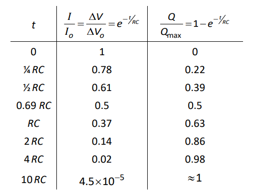
Note that the half-life of the charging (and discharging) process is approximately $0.69 R C$
Note also that while $Q_{\max }$ depends on the voltage applied, the rate of charging and discharging depend only on the resistance and capacitance in the circuit.
Discharging a Capacitor
Just as a capacitor charges gradually, it also discharges graduall Imagine we have a circuit like the one at the right.
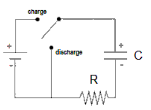
When the switch is in the “charge” position, the battery charges the capacitor. When the switch is flipped to the “discharge” position, the battery is switched out and the circuit contains only the
capacitor and the resistor. When this happens, the capacitor discharges (loses its charge). The capacitor acts as a temporary voltage source, and current temporarily flows out of the capacitor through the resistor.
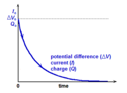
(Note again that the graphs are not to scale; the $y$-axis scale and units are necessarily different for current, voltage and charge.)
The driving force for this temporary current is the repulsion from the stored charges in the capacitor. As charge leaves the capacitor there is less repulsion, which causes the voltage and current to decrease exponentially along with the charge.
The equations for discharging a capacitor are therefore identical in form to the equations for charging it:
$
\Delta V=\Delta V_o e^{-t / R C} \quad Q=Q_o e^{-t / R C} \quad I=I_o e^{-t / R C}
$
or, dividing each by its value at time zero:
$
\frac{\Delta V}{\Delta V_o}=\frac{Q}{Q_o}=\frac{I}{I_o}=e^{-t / R C}
$
Again the time constant, $R C$, is the relative amount of time it takes for the charge remaining in the capacitor and the voltage and current in the circuit to decay. (Refer to the table on page 402 .)
Sample Problem
Q: A circuit has a 9V battery, an open switch, a 1kΩ resistor, and a capacitor in series. The capacitor has no residual charge.
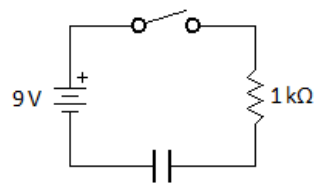
When the switch is closed, the charge in the capacitor climbs to $86 \%$ of its maximum value in $50 \mathrm{~ms}$. What is the capacitance of the capacitor?
Answer/Explanation
A: The charge increases at the rate of:
$
Q(t)=Q_{\max }\left(1-e^{-t / R C}\right)
$
We are given that $\frac{Q}{Q_{\max }}=0.86, t=0.05 \mathrm{~s}$, and $R=1000 \Omega$.
\begin{aligned}
& \frac{Q}{Q_{\max }}=1-e^{-t / / c} \\
& 0.86=1-e^{-0.05 / 1000 C} \\
& -0.14=-e^{-0.05 / 1000 c} \\
& \ln (0.14)=\ln \left(e^{-0.05 / 1000 C}\right)=\frac{-0.05}{1000 C} \\
& -1.97=\frac{-0.05}{1000 C} \\
& 1970 C=0.05 \\
& C=\frac{0.05}{1970}=2.5 \times 10^{-5} \mathrm{~F}=25 \mu \mathrm{F}
\end{aligned}
Note that we could have solved this problem by using the table on page 402 to see that the capacitor is $86 \%$ charged $\left(\frac{Q}{Q_{\max }}=0.86\right)$ when $t=2 R C$.