Topics covered in this chapter:
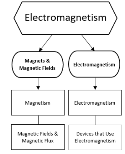
Magnetism
Notes:
magnet: a material with electrons that can align in a manner that attracts or repels other magnets.
A magnet has two ends or “poles”, called “north” and “south”. If a magnet is allowed to spin freely, the end that points toward the north on Earth is called the north end of the magnet. The end that points toward the south on Earth is called the south end of the magnet. (The Earth’s magnetic poles are near, but not in exactly the same place as its geographic poles.)
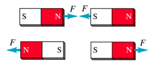
All magnets have a north and south pole. As with charges, opposite poles attract, and like poles repel.
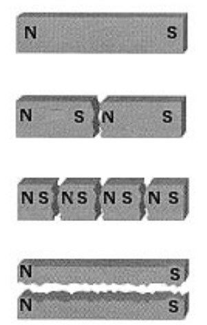
If you were to cut a magnet in half, each piece would be a magnet with its own north and south pole:
Electrons and Magnetism
Magnetism is caused by unpaired electrons in atoms. Electrons within atoms reside in energy regions called “orbitals”. Each orbital can hold up to two electrons.
If two electrons share an orbital, they have opposite spins. (Note that the electrons are not actually spinning. “Spin” is the term for the intrinsic property of certain subatomic particles that is believed to be responsible for magnetism.) This means that if one electron aligns itself with a magnetic field, the other electron in the same orbital becomes aligned to oppose the magnetic field, and there is no net force.
However, if an orbital has only one electron, that electron is free to align with the magnetic field, which causes an attractive force between the magnet and the magnetic material. For example, as you may have learned in chemistry, the electron configuration for iron is:
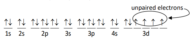
The inner electrons are paired up, but four of the electrons in the 3d sublevel are unpaired, and are free to align with an external magnetic field.
Magnetic measurements and calculations involve fields that act over 3-dimensional space and change continuously with position. This means that most calculations relating to magnetic fields need to be represented using multivariable calculus, which is beyond the scope of this course.
magnetic permeability (magnetic permittivity): the ability of a material to support the formation of a magnetic field. Magnetic permeability is represented by the variable $\mu$. The magnetic permeability of empty space is $\mu_0=4 \pi \times 10^{-7} \frac{\mathrm{N}}{\mathrm{A}^2}$.
diamagnetic: a material whose electrons cannot align with a magnetic field. Diamagnetic materials have very low magnetic permeabilities.
paramagnetic: a material that has electrons that can align with a magnetic field. Paramagnetic materials have relatively high magnetic permeabilities.
ferromagnetic: a material that can form crystals with permanently-aligned electrons, resulting in a permanent magnet. Ferromagnetic materials can have very high magnetic permeabilities. Some naturally-occurring materials that exhibit ferromagnetism include iron, cobalt, nickel, gadolinium, dysprosium, and magnetite $\left(\mathrm{Fe}_3 \mathrm{O}_4\right)$.
magnetic susceptibility: a measure of the degree of magnetization of a material when it is placed into a magnetic field.
Magnetic Fields & Magnetic Flux
Notes:
magnetic field $(\overrightarrow{\boldsymbol{B}})$ : a force field (region in which a force acts on objects that have a certain property) in which magnetic attraction and repulsion are occurring.
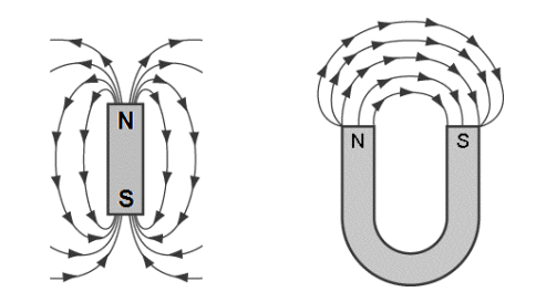
Similar to an electric field, we represent a magnetic field by drawing field lines. Magnetic field lines point from the north pole of a magnet toward the south pole, and they show the direction that the north end of a compass or magnet would be deflected if it was placed in the field:
The strength of a magnetic field is measured in teslas $(T)$, named after the physicist Nikola Tesla. One tesla is the magnetic field strength necessary to produce one newton of force when a particle that has a charge of one coulomb is moved through the magnetic field at a velocity of one meter per second. Because of the relationship between magnetism, forces, and electricity, one tesla can be expressed as many different combinations of units:
$
1 \mathrm{~T} \equiv 1 \frac{\mathrm{V} \cdot \mathrm{s}}{\mathrm{m}^2} \equiv 1 \frac{\mathrm{N}}{\mathrm{A} \cdot \mathrm{m}} \equiv 1 \frac{\mathrm{J}}{\mathrm{A} \cdot \mathrm{m}^2} \equiv 1 \frac{\mathrm{kg}}{\mathrm{C} \cdot \mathrm{s}} \equiv 1 \frac{\mathrm{N} \cdot \mathrm{s}}{\mathrm{C} \cdot \mathrm{m}} \equiv 1 \frac{\mathrm{kg}}{\mathrm{A} \cdot \mathrm{s}^2}
$
The Earth’s Magnetic Field
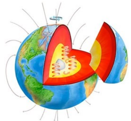
The inner and outer core of the Earth are made of iron, which has a high magnetic susceptibility. The very high temperature of the inner core causes convection currents in the molten iron in the outer core. The rapid rotation of the Earth causes the molten iron in the outer core to swirl. The swirling iron causes a magnetic field over the entire planet
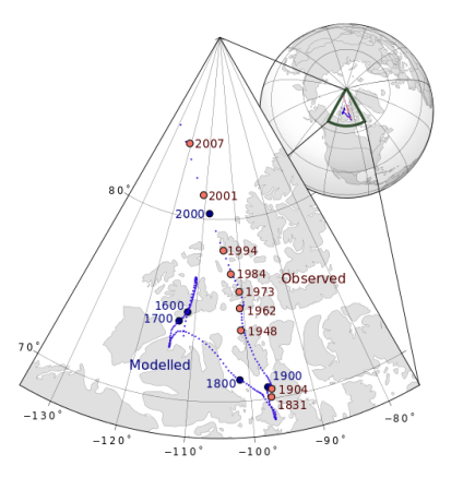
Because the core of the Earth is in constant motion, the Earth’s magnetic field is constantly changing. The exact location of the Earth’s magnetic north and south poles varies by about $80 \mathrm{~km}$ over the course of each day because of the rotation of the Earth. Its average location (shown on the map of Northern Canada below) drifts by about $50 \mathrm{~km}$ each year:
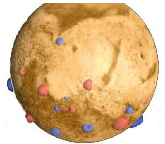
Not all planets have a planetary magnetic field. Mars, for example, is believed to have once had a planetary magnetic field, but the planet cooled off enough to disrupt the processes that caused it. Instead, Mars has some very strong localized magnetic fields that were formed when minerals cooled down in the presence of the planetary magneticfield. In this picture, the blue and red areas represent regions with strong localized magnetic fields. On Mars, a compass could not be used in the ways that we use a compass on Earth; if you took a compass to Mars, the needle would point
either toward or away from each these regions. Jupiter, on the other hand, has a planetary magnetic field twenty times as strong as that of Earth. This field may be caused by water with dissolved electrolytes or by liquid hydrogen.
Recall that the north pole of a magnet is the end that points toward the north on Earth. This must mean that if the Earth is a giant magnet, one of its magnetic poles must be near the geographic north pole, and the other magnetic pole must be near the geographic south pole.
For obvious reasons, the Earth’s magnetic pole near the north pole is called the Earth’s “north magnetic pole” or “magnetic north pole”. Similarly, the Earth’s magnetic pole near the south pole is called the Earth’s “south magnetic pole” or “magnetic south pole”.
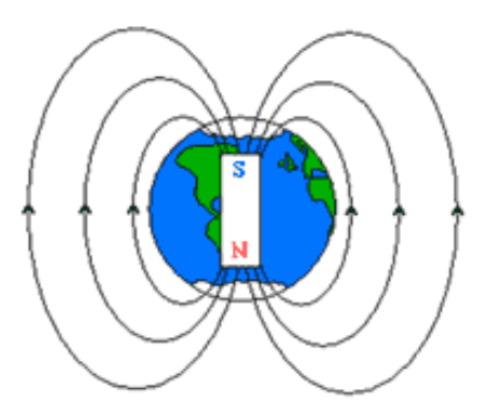
However, because the north pole of a magnet points toward the north, the Earth’s north magnetic pole (meaning its location) must therefore be the south pole of the giant magnet that is the Earth.
Similarly, because the south pole of a magnet points toward the south, the Earth’s south magnetic pole (meaning its location) must therefore be the north pole of the giant Earth-magnet.
Unfortunately, the term “magnetic north pole,” “north magnetic pole” or any other similar term almost always means the magnetic pole that is in the north part of the Earth. There is no universally-accepted way to name the poles of the Earth-magnet.
Magnetic Flux
flux: the flow of fluid, energy or particles across a given area.
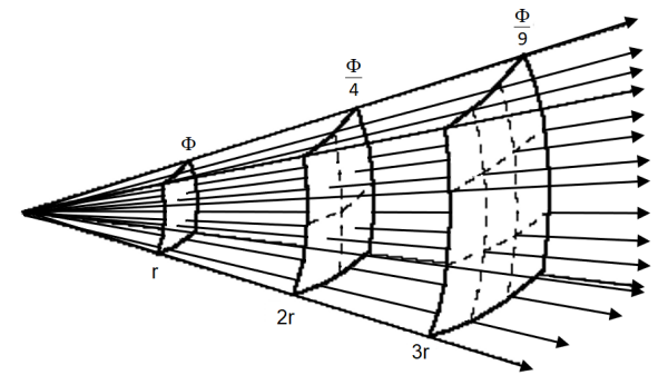
If a quantity (such as a magnetic field) originates from a point, the field spreads out and the amount of flux through a given area decreases as the square of the distance from that point.
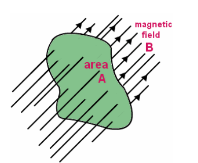
magnetic flux (Φ): the total amount of a magnetic field that passes through a surface. Stronger magnetic fields are generally shown with a higher density of field lines. Using this representation, you can think of the magnetic flux as the number of field lines that pass through an area. The equation for magnetic flux is Faraday’s Law, named for the English physicist Michael Faraday. The equation is usually presented as a surface integral, but in algebraic form it looks like the following:
$
\Phi=\overrightarrow{\boldsymbol{B}} \cdot \overrightarrow{\boldsymbol{A}}
$
where:
$
\begin{aligned}
\Phi & =\text { magnetic flux }(\mathrm{Wb}) \\
\vec{B} & =\text { strength of magnetic field }(T)
\end{aligned}
$
$\overrightarrow{\boldsymbol{A}}=$ area of the region of interest that the magnetic field passes through $\left(m^2\right)$
The unit for magnetic flux is the weber (Wb). One tesla is one weber per square meter.
$
1 \mathrm{~T} \equiv 1 \frac{\mathrm{Wb}}{\mathrm{m}^2}
$
Electromagnetism
Notes:
A changing electric field produces a magnetic field, and a changing magnetic field produces an electric field. These actions can produce magnetic forces or electromagnetic forces (emf).
Magnetic Fields and Moving Charges
Like gravitational and electric fields, a magnetic field is a force field. (Recall that force fields are vector quantities, meaning that they have both magnitude and direction.) The strength of a magnetic field is measured in teslas (T), named after the Serbian-American physicist Nikola Tesla.
$
1 \mathrm{~T}=1 \frac{\mathrm{N}}{\mathrm{A} \cdot \mathrm{m}}
$
In the 1830s, physicists Michael Faraday and Joseph Henry each independently discovered that an electric current could be produced by moving a magnet through a coil of wire, or by moving a wire through a magnetic field. This process is called electromagnetic induction.
If we move a conductive rod or wire that has length $L$ at a velocity $v$ through a magnetic field of strength $B$, the magnetic forces send positive charges to one end of the rod and negative charges to the other. This creates a potential difference (emf) between the ends of the rod:
$
\varepsilon=V B L
$
If the rod or wire is part of a closed loop (circuit), then the induced $\varepsilon$ produces a current around the closed loop. From Ohm’s Law $\varepsilon=I R$, we get:
$
I=\frac{\varepsilon}{R}=\frac{v B L}{R}
$
Forces and Moving Charges
The force, $\overrightarrow{\boldsymbol{F}}$ on a charge $q$ moving through a magnetic field $\overrightarrow{\boldsymbol{B}}$ with a velocity $\overrightarrow{\boldsymbol{v}}$ is given by the equation:
$
\overrightarrow{\boldsymbol{F}}=q(\overrightarrow{\boldsymbol{v}} \times \overrightarrow{\boldsymbol{B}}) \quad \text { and } \quad F=q v B \sin \theta
$
Recall that current is just a flow of charges, which means that an electric current moving through a magnetic field creates a force on the wire carrying the current.
Recall that $\overrightarrow{\boldsymbol{I}}=\frac{\Delta Q}{t}$ and $\overrightarrow{\boldsymbol{v}}=\frac{\overrightarrow{\boldsymbol{d}}}{t}=\frac{\ell}{t}$, where $\ell$ is the length (distance) of the wire that passes through the magnetic field. This means that $q \overrightarrow{\boldsymbol{v}}=\ell \overrightarrow{\boldsymbol{I}}$, which we can use to create an equivalent equation:
$
\overrightarrow{\boldsymbol{F}}=\ell(\overrightarrow{\boldsymbol{I}} \times \overrightarrow{\boldsymbol{B}}) \quad \text { and } \quad F=\ell I B \sin \theta
$
Note that the direction of the cross products $\overrightarrow{\boldsymbol{v}} \times \overrightarrow{\boldsymbol{B}}$ and $\overrightarrow{\boldsymbol{I}} \times \overrightarrow{\boldsymbol{B}}$ can be determined using the right-hand rule.
A current passing through a magnetic field would be represented like this:
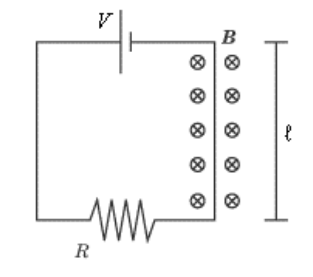
In the above diagram, the battery has voltage $V$, the resistor has resistance $R$, and the length of wire passing through the magnetic field is $l$.
The magnetic field strength is $\boldsymbol{B}$, and the field itself is denoted by the symbols
$\otimes \otimes \otimes \otimes \otimes$ which denote a magnetic field going into the page. (A field
coming out of the page would be denoted by $\odot \odot \odot \odot \odot \odot \odot$ instead. Think of the circle as an arrow inside a tube. The dot represents the tip of the arrow facing toward you, and the ” $\mathrm{X}$ ” represents the fletches (feathers) on the tail of the arrow facing away from you.)
For example, suppose we were given the following for the above diagram:
$
\begin{aligned}
\overrightarrow{\boldsymbol{B}} & =4.0 \times 10^{-5} \mathrm{~T} \\
V & =30 \mathrm{~V} \\
R & =5 \Omega \\
\ell & =2 \mathrm{~m}
\end{aligned}
$
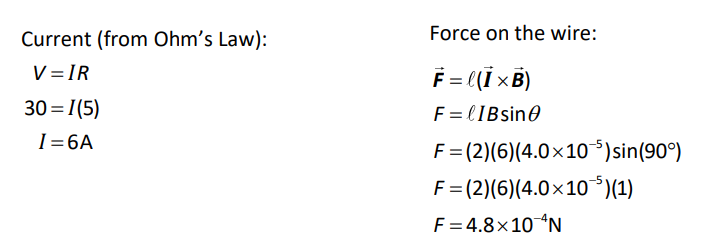
If the current is going upward through the magnetic field, and the magnetic field is pointing into the paper, then the right-hand rule tells us that the force would be directed to the left.
Magnetic Field Produced by Electric Current
An electric current moving through a wire also produces a magnetic field around the wire:
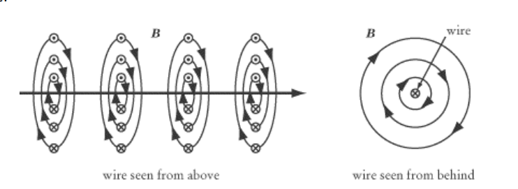
This time, we use the right-hand rule with our thumb pointing in the direction of the current, and our fingers curl in the direction of the magnetic field.
The strength of the magnetic field produced is given by the formula:
$
B=\frac{\mu_o}{2 \pi} \frac{I}{r}
$
where $B$ is the strength of the magnetic field, $\mu_0$ is the magnetic permeability of free space, $I$ is the current, and $r$ is the distance from the wire. (The variable $r$ is used because the distance is in all directions, which means we would use polar or cylindrical coordinates.)
EMF Produced by Changing Magnetic Flux
A changing magnetic field produces an electromotive force (emf) in a loop of wire. This emf is given by the equation:
$
\varepsilon=-\frac{d \Phi}{d t}=-\frac{\Delta \Phi}{t}
$
If we replace the loop of wire with a coil that has $n$ turns, the equation becomes:
$
\varepsilon=-n \frac{d \Phi}{d t}=-n \frac{\Delta \Phi}{t}
$
Combined Electric and Magnetic Fields
Recall that the force on a charged particle due to an electric field is:
$
\overrightarrow{\boldsymbol{F}}_e=q \overrightarrow{\boldsymbol{E}}
$
and that the force on a charged particle due to a magnetic field is:
$
\overrightarrow{\boldsymbol{F}}_B=q(\overrightarrow{\boldsymbol{v}} \times \overrightarrow{\boldsymbol{B}})
$
Therefore, the force on a charged particle that interacts simultaneously with an electric field and a magnetic field must be the sum of the two:
$
\overrightarrow{\boldsymbol{F}}_{E M}=q(\overrightarrow{\boldsymbol{E}}+\overrightarrow{\boldsymbol{v}} \times \overrightarrow{\boldsymbol{B}})
$
An application of this combination is a particle sorter, which allows only particles with a given velocity to pass through.
Particles that enter a mass spectrometer must have the correct velocity in order for the mass spectrometer to be able to separate the particles properly. Before the particles enter the mass spectrometer, they first pass through a particle sorter, which applies opposing electric and magnetic forces to the particle:
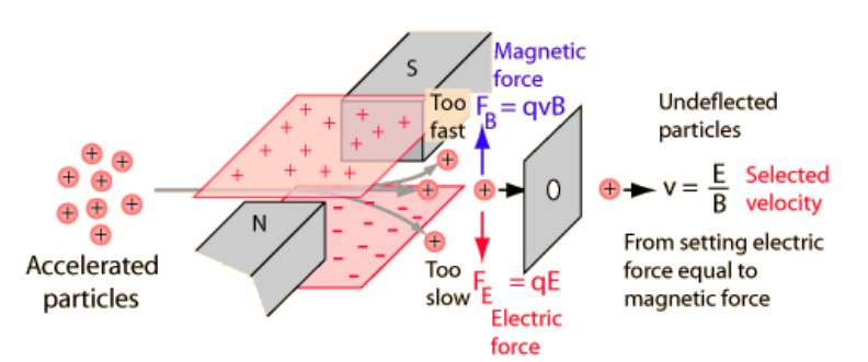
If the particles are moving too quickly, the magnetic force is stronger and the particles are deflected upwards. If the particles are moving too slowly, the electric force is stronger and the particles are deflected downwards. Particles with the desired velocity experience no net force and are not deflected.
Sample Problem:
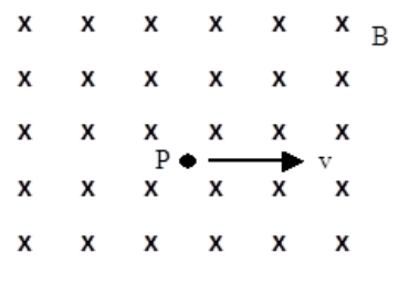
Q: A proton has a velocity of $1 \times 10^5 \frac{\mathrm{m}}{\mathrm{s}}$ to the right when it is at point $P$ in a uniform magnetic field of $0.1 \mathrm{~T}$ that is directed into the page. Calculate the force (magnitude and direction) on the proton, and sketch its path.
Answer/Explanation
A: The force on the proton is given by:
$
\overrightarrow{\boldsymbol{F}}_B=q(\overrightarrow{\boldsymbol{v}} \times \overrightarrow{\boldsymbol{B}})=q v B \sin \theta
$
Because the velocity of the particle and the direction of the magnetic field are perpendicular, $\sin \theta=\sin \left(90^{\circ}\right)=1$ and therefore the magnitude of $F_B=q v B$.
$
\begin{aligned}
& F_B=q v B \\
& F_B=\left(1.6 \times 10^{-19}\right)\left(1 \times 10^5\right)(0.1) \\
& F_B=1.6 \times 10^{-15} \mathrm{~N}
\end{aligned}
$
The direction is given by the right-hand rule. Start with the fingers of your right hand pointing straight in the direction of velocity (to the right) and rotate your right hand until you can bend your fingers toward the magnetic field (into the page). Your thumb will be pointing upwards, which means that the force on a positively charged particle moving to the right is upwards. (Note that if the particle had been negatively charged, it would have moved in the opposite direction.)
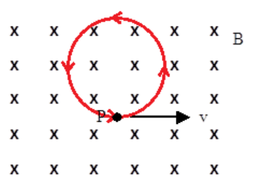
However, note that the action of the force causes a change in the direction of the proton’s velocity, and the change in the direction of the proton’s velocity changes the direction of the force. This feedback loop results in the proton moving in a continuous circle.
Devices that Use Electromagnetism
Notes:
Solenoid
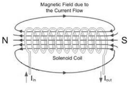
A solenoid is a coil made of fine wire. When a current is passed through the wire, it produces a magnetic field through the center of the coil. When a current is applied, a permanent magnet placed in the center of the solenoid will be attracted or repelled and will move. One of the most common uses of a solenoid is for electric door locks.
Electromagnet
An electromagnet is a device that acts as magnet only when electric current is flowing through it.
An electromagnet is made by placing a soft iron core in the center of a solenoid. The high magnetic permeability of iron causes the resulting magnetic field to become thousands of times stronger:
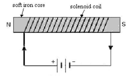
Because the iron core is not a permanent magnet, the electromagnet only works when current is flowing through the circuit. When the current is switched off, the electromagnet stops acting like a magnet and releases whatever ferromagnetic objects might have been attracted to it.
Of course, the above description is a simplification. Real ferromagnetic materials such as iron usually experience magnetic remanence, meaning that some of the electrons in the material remain aligned, and the material is weakly magnetized.
While magnetic remanence is undesirable in an electromagnet, it is the basis for magnetic computer storage media, such as audio and computer tapes and floppy and hard computer disks. To write information onto a disk, a disk head (an electromagnetic that can be moved radially) is pulsed in specific patterns as the disk spins. The patterns are encoded on the disk as locally magnetized regions.
When encoded information is read from the disk, the moving magnetic regions produce a changing electric field that causes an electric current in the disk head.
Motor
The force produced by a moving current in a magnetic field can be used to cause a loop of wire to spin:
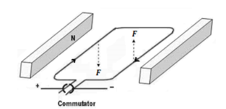
A commutator is used to reverse the direction of the current as the loop turns, so that the combination of attraction and repulsion always applies force in the same direction. If we replace the loop of wire with an electromagnet (a coil of wire wrapped around a material such as iron that has both a high electrical conductivity and a high magnetic permeability), the electromagnet will spin with a strong force.
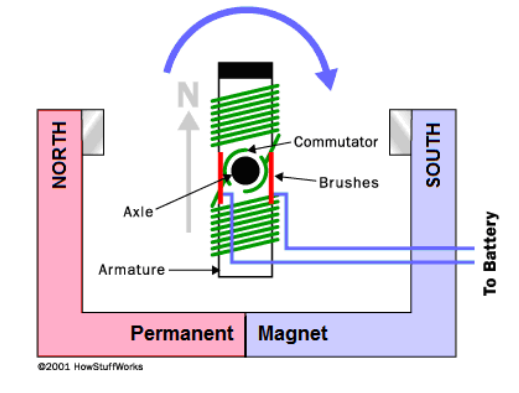
An electromagnet that spins because of its continuously switching attraction and repulsion to the magnetic field produced by a separate set of permanent magnets is called a motor. An electric motor turns electric current into rotational motion, which can be used to do work.
Generator
A generator uses the same components and operates under the same principle as a motor, except that a mechanical force is used to spin the coil. When the coil moves through the magnetic field, it produces an electric current. Thus a generator is a device that turns rotational motion (work) into an electric current.
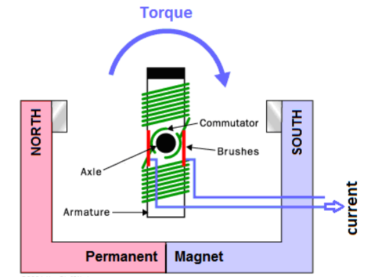
Recall from the previous section that Lenz’s Law gives the emf produced by the generator. Because the coil is rotating through a uniform magnetic field, the magnetic flux through the coil is constantly changing, which means calculus is needed to calculate the emf produced.
$
\varepsilon=-n \frac{d \Phi}{d t}
$
Inductor (Transformer)
Because electric current produces a magnetic field, a ring made of a ferromagnetic material can be used to move an electric current. An inductor (transformer) is a device that takes advantage of this phenomenon in order to increase or decrease the voltage in an AC circuit.
The diagram below shows an inductor or transformer.
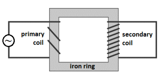
The current on the input side (primary) generates a magnetic field in the iron ring. The magnetic field in the ring generates a current on the output side (secondary).
In this particular transformer, the coil wraps around the output side more times than the input. This means that each time the current goes through the coil, the magnetic field adds to the electromotive force (voltage). This means the voltage will increase in proportion to the increased number of coils on the output side.
However, the magnetic field on the output side will produce less current with each turn, which means the current will decrease in the same proportion:
$
\begin{aligned}
\frac{\# \text { turns }_{\text {in }}}{\text { \#turns }} \text { out } & =\frac{V_{\text {in }}}{V_{\text {out }}}=\frac{I_{\text {out }}}{I_{\text {in }}} \\
P_{\text {in }} & =P_{\text {out }}
\end{aligned}
$
A transformer like this one, which produces an increase in voltage, is called a step-up transformer; a transformer that produces a decrease in voltage is called a step-down transformer.
Sample Problem:
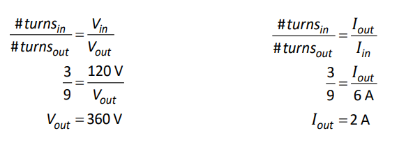
If the input voltage to the following transformer is 120 V, and the input current is 6 A, what are the output voltage and current?
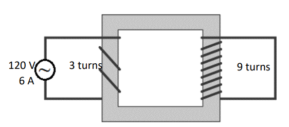
The voltage on either side of a transformer is proportional to the number of turns in the coil on that side. In the above transformer, the primary has 3 turns, and the secondary coil has 9 turns. This means the voltage on the right side will be $\frac{9}{3}=3$ times as much as the voltage on the left, or $360 \mathrm{~V}$. The current will be $\frac{3}{9}=\frac{1}{3}$ as much, or $2 \mathrm{~A}$.
We can also use:
Mass Spectrometer
A mass spectrometer is a device uses the path of a charged particle in a magnetic field to determine its mass.
The particle is first selected for the desired velocity, as described on page 427. Then the particle enters a region where the only force on it is from the applied magnetic field. (In the example below, the magnetic field is directed out of the page.)
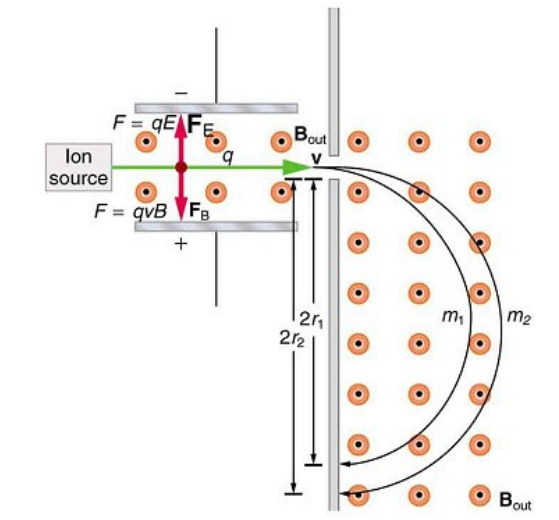
The magnetic field applies a force on the particle perpendicular to its path. As the particle’s direction changes, the direction of the applied force changes with it, causing the particle to move in a circular path.
The path of the particle is the path for which the centripetal force (which you may recall from physics 1 ) is equal to the magnetic force:
$
\begin{aligned}
F_B & =F_c \\
q v B & =\frac{m v^2}{r} \\
r & =\frac{m v^2}{q v B}=\frac{m v}{q B}
\end{aligned}
$
Thus if the particles are all ions with the same charge and are selected for having the same speed, the radius of the path will be directly proportional to the mass of the particle.