Question
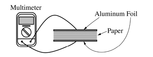
An experiment is designed to measure the dielectric constant of paper that has an area A = 0.060 m2 . Using aluminum foil, two parallel plates are created with the same area as the paper. Five hundred sheets of paper are placed between the aluminum foil plates to create a parallel plate capacitor, as shown in the figure above. Using a multimeter, the capacitance C of the capacitor is measured. The number of sheets and the total thickness d of the stack of paper are recorded. The experiment is repeated, reducing the number of sheets of paper each time. The data are recorded in the table below.
| Sheets of Paper | d(m) | C(F) | ||
| 500 | 0.045 | 6.5×10⁻¹¹ | ||
| 400 | 0.036 | 7.4×10⁻¹¹ | ||
| 300 | 0.027 | 8.9×10⁻¹¹ | ||
| 200 | 0.018 | 11.9×10⁻¹¹ | ||
| 100 | 0.010 | 21.0×10⁻¹¹ |
(a) Indicate below which quantities should be graphed to yield a straight line whose slope could be used to calculate a numerical value for the dielectric constant of the paper.
Vertical axis: ____________
Horizontal axis: __ __________
Use the remaining columns in the table above, as needed, to record any quantities that you indicated that are not given. Label each column you use and include units.
(b) Plot the data points for the quantities indicated in part (a) on the graph below. Clearly scale and label all axes, including units if appropriate. Draw a straight line that best represents the data.
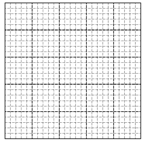
(c) Using the straight line, calculate a dielectric constant for the paper.
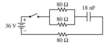
The student now makes a capacitor using the same aluminum foil plates and just one sheet of paper. Using the experimentally determined dielectric constant, the student calculates the capacitance to be 18 nF. The student uses this uncharged capacitor to build a circuit using wire, a 36 V battery, 3 identical 80 Ω resistors, and an open switch, as shown in the figure above.
(d) Calculate the current in the battery immediately after the switch is closed.
(e) Determine the time constant for this circuit.
(f) Students A and B measure the time it takes after the switch is closed for the voltage across the capacitor to reach half its maximum value and find that it is longer than expected.
i. Student A assumes that the capacitance value is correct. Would Student A conclude that the resistance value is larger or smaller than measured?
____ Larger than measured ____ Smaller than measured
Explain experimentally what could account for this.
ii. Student B assumes that the resistance value is correct. Would Student B conclude that the capacitance value is larger or smaller than measured?
____ Larger than measured ____ Smaller than measured
Explain experimentally what could account for this.
Answer/Explanation
Ans:
ε0 = 8.85 × 10⁻¹²
\(\frac{C^{2}}{\frac{Nm^{2}}{m}}.m^{2}\)
\(C = \frac{K\varepsilon _{0}A}{d}\)
| Sheets of Paper | d(m) | C(F) | \(\frac{\varepsilon _{0}A}{d}\cdot \left ( \frac{C^{2}}{Nm} \right )\) | |
| 500 | 0.045 | 6.5×10⁻¹¹ | 1.18×10⁻¹¹ | |
| 400 | 0.036 | 7.4×10⁻¹¹ | 1.475×10⁻¹¹ | |
| 300 | 0.027 | 8.9×10⁻¹¹ | 1.97×10⁻¹¹ | |
| 200 | 0.018 | 11.9×10⁻¹¹ | 2.95×10⁻¹¹ | |
| 100 | 0.010 | 21.0×10⁻¹¹ | 5.31×10⁻¹¹ |
(a)
\(F = \frac{K\frac{C^{2}}{Nm^{2}}(m^{2})}{m}\)
\(\frac{C^{2}}{Nm}\)
(b)
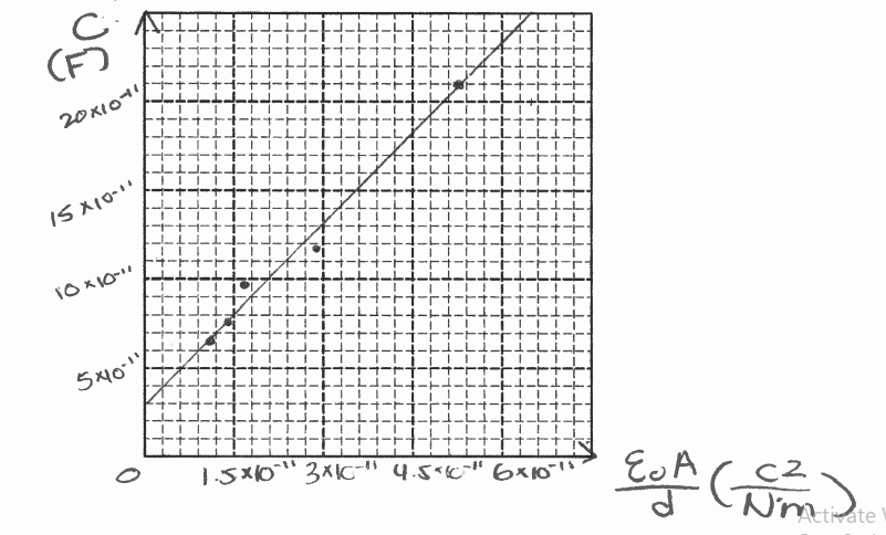
(c)
(1.5×10⁻¹¹ , 8×10-11)
(3×10-11 , 13×10-11)
\(K = \frac{13\times 10^{-11}F – 8\times 10^{-11}F}{3\times 10^{-11}\frac{C^{2}}{Nm}-1.5\times 10^{-11}\frac{C^{2}}{Nm}}\)
\(=3.33 \frac{FNm}{C^{2}}\)
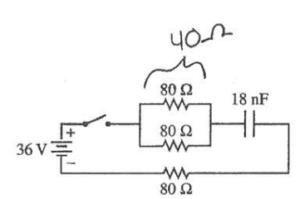
(d)
Req = 40Ω + 80Ω = 120Ω
\(I = \frac{V}{R}= \frac{3Gv}{120\Omega }=.3A\)
(e)
τ = RC
= 120 Ω (18 × 10-9 F)
= 2.16 × 10⁻⁶ Ω. F
(f) i.
__√___ Smaller than measured
Resistance in the wire < could area it for this
ii.
__√___ Larger than measured
\(C = \frac{\varepsilon _{0}A}{d}\)
The student could have measured the distance wrong when calculating capacitance
Question
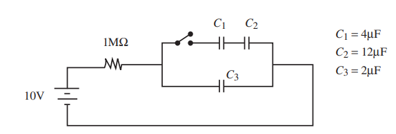
A 1 MΩ resistor is connected to the network of capacitors shown above. The circuit is hooked to a 10-V battery. The capacitors are initially uncharged. The battery is connected, and the switch is closed at time t = 0.
(a) Determine the equivalent capacitance of C1, C2, and C3
(b) Determine the charge on and voltage across each capacitor after a long time has elapsed.
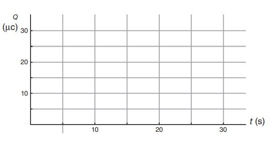
(c) On the axes below, sketch the total charge on C3 as a function of time.
(d) After the capacitors have been fully charged, the switch is opened, disconnecting C1 and C2 from the circuit. What happens to the voltage across and charge on C3? Justify your answer.
Answer/Explanation
(a) The series capacitors add inversely ,
\(\frac{1}{4μF}+\frac{1}{12μF}=\frac{1}{C_{eq}}\)
so \(C_{eq}\) for the series capacitors is 3 μF. The parallel capacitor just adds in algebraically, so the equivalent capacitance for the whole system is 5 μF.
(b)
After a long time, the resistor is irrelevant; no current flows because the fully charged capacitors block direct current. The voltage across \(C_3\) is 10 V (because there’s no voltage drop across the resistor without any current). By Q = CV the charge on \(C_3\) is 20 μC. Treating \(C_1\) and \(C_2\) in series; the equivalent capacitance is 3 μF, the voltage is 10 V
(in parallel with \(C_3\)). The charge on the equivalent capacitance of \(C_1\) and \(C_2\) is 30 μC; thus the charge on \(C_1\) = 30 μC, and the charge on \(C_2\) is also 30 μC (charge on series capacitors is the same).Using Q = CV, the voltage across \(C_1\) is 7.5 V. Using Q = CV, the voltage across C2 is 2.5 V.
(c)
For a graph that starts at Q = 0. For a graph that asymptotically approaches20 μC (or whatever charge was calculated for \(C_3\) in part b). For calculating the time constant of the
circuit, RC = 5 s. For the graph reaching about 63% of its maximum charge after one time constant.
(d)
For recognizing that the voltage does not change. For explaining that if voltage changed, then Kirchoff’s voltage rule would not be valid around a loop including \(C_3\) and the battery (or explaining that voltage is the same across parallel components, so if one is disconnected the other’s voltage is unaffected).