Question
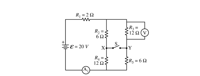
A circuit is created with an ideal battery and five resistors with the values shown in the figure above. An open switch is shown that can connect points X and Y. A voltmeter V and an ammeter \(A_1\) are also shown in the figure.
(a) The switch is in the open position.
i. Calculate the current measured by the ammeter \(A_1\) .
ii. Calculate the potential difference measured by the voltmeter V.
(b) The switch is now moved to the closed position.
i. Calculate the current measured by the ammeter\ (A_1\) .
ii. Calculate the potential difference measured by the voltmeter V.
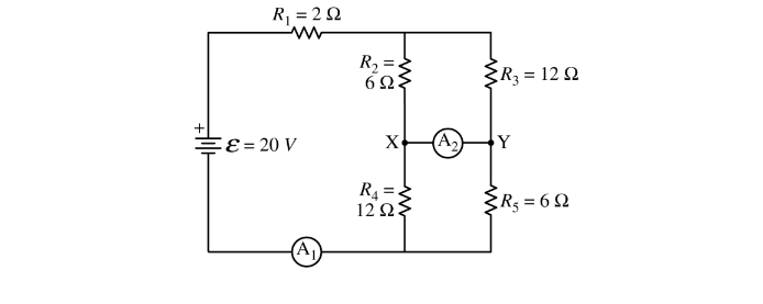
A student wants to determine if there is a current in the closed switch. The switch is now replaced with ammeter \(A_2\) between points X and Y. The ammeter acts as a closed switch and can measure the current, if any, between the two points.
(c)
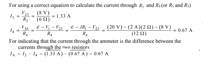
i. Calculate the current measured by ammeter\( A_2\) .
ii. Indicate the direction of the current, if any, through the ammeter\( A_2\) .
Left______ Right_________ Undefined, because the current is zero
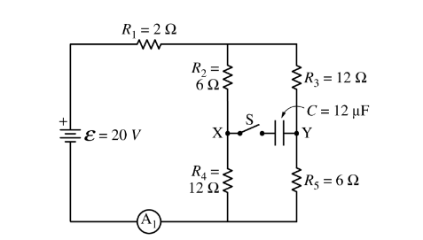
(d) The ammeter A_2 is replaced with switch S and capacitor C = 12 Fμ , as shown in the figure above. Switch S is closed.
i. Calculate the charge stored on the positive plate of capacitor C a long time after switch S is closed.
ii. Which point, X or Y, is at a higher electric potential? X Y Justify your answer.
Answer/Explanation
(a)(i)
(ii) For correct substitution (consistent with a(i)) into a correct equation to calculate the potential difference across \(R_3\) \(V_p = \varepsilon − V_1 = \varepsilon − IR_1 = (20 V) – (1.82 A)(2 \Omega ) = 16.4 V\) \(I_{35}=\frac{V_p}{R_{35}}=\frac{ (16.4 V)}{ (18)}= 0.91 A\) \(V_3=I_{35}R_3=(0.91 A)(12 \Omega ) = 10.9 V\)
b.(i)
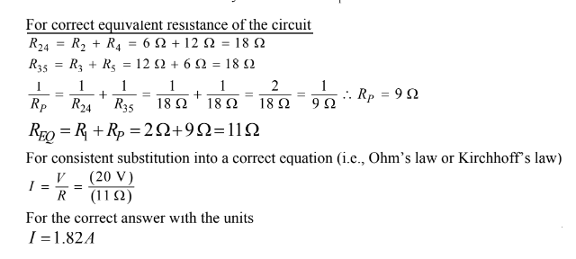
For the correct equivalent resistance of the circuit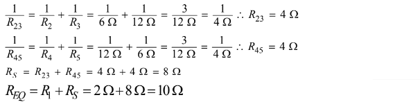
For consistent substitution into a correct equation (i.e., Ohm’s law or Kirchhoff’s law)
\(I=\frac{v}{r} \rightarrow \frac{20}{10}=2A\)
(ii)
For correct substitution (consistent with b(i) ) into a correct equation to calculate the potential difference across \(R_3\)
\(V_3=I_{35}R_3=(2 A)(4 \Omega ) = 8 V\)
(c)
i)
ii) For selecting “Right” Note: If a student calculated IA in Part c(i) to be zero then the consistent answer of “Undefined” earns 1 point.
(d) i)
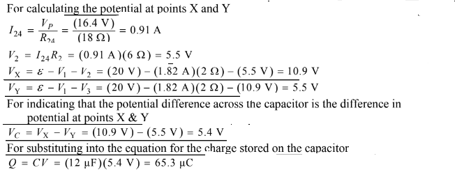
ii) Selecting “X” For a correct justification Example: The point X is at higher potential because the current flows to the right. The current flows from high potential to low potential.
Example: The potential at X is 10.9 V and the potential at Y is 5.5 V. So point X is at the higher potential.
Question
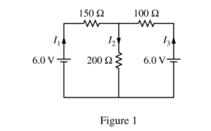
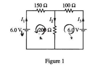
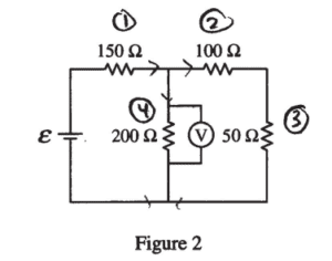
The circuit shown above is constructed with two 6.0 V batteries and three resistors with the values shown. The currents I1 , I2 , and I3 in each branch of the circuit are indicated.
(a)
i. Using Kirchhoff’s rules, write, but DO NOT SOLVE, equations that can be used to solve for the current in each resistor.
ii. Calculate the current in the 200 Ω resistor.
iii. Calculate the power dissipated by the 200 Ω resistor.
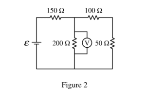
The two 6.0 V batteries are replaced with a battery with voltage ε and a resistor of resistance 50 Ω, as shown above. The voltmeter V shows that the voltage across the 200 Ω resistor is 4.4 V.
(b) Calculate the current through the 50 Ω resistor.
(c) Calculate the voltage e of the battery.
(d)
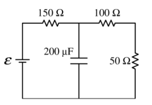
i. The 200 Ω resistor in the circuit in Figure 2 is replaced with a 200 Fμ capacitor, as shown on the right, and the circuit is allowed to reach steady state. Calculate the current through the 50 Ω resistor.
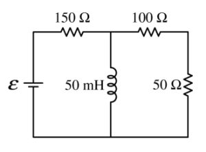
ii. The 200 W resistor in the circuit in Figure 2 is replaced with an ideal 50 mH inductor, as shown on the right, and the circuit is allowed to reach steady state. Is the current in the 50 W resistor greater than, less than, or equal to the current calculated in part (b) ?
____ Greater than ____ Less than ____ Equal to
Justify your answer.
Answer/Explanation
Ans:
(a) i.
Loop 1: 6 – 150 I1 – 200 I2 = 0
Loop 2: 6 – 100 I3 – 200 I2 = 0
I1 + I3 = I2
ii.
I1 = I2 – I3
– 6 – 150 I2 + 150 I3 – 200 I2 = 0
6 – 150 I3 – 200 I2 = 0
——————————————
-150I2 + 250 I3 = 0
I3 = 0.6 I2
6 – 100 (0.6I2 ) – 200 I2 = 0
I2 = 0.023 (A)
iii.
P = I2R = (0.023)2 (200) = 0.107 (w)
(b)
R25 = 100 + 50 = 150 Ω
V23 = V4 = 4.4 (V)
\(I_{2}=I_{3}=\frac{V_{23}}{R_{23}}=\frac{4.4}{150}=0.029 (A)\)
(c)
\(I_{1}=I_{2}+I_{4}=I_{2}+\frac{V_{4}}{R_{4}}=0.029+\frac{4.4}{200}\)
= 0.051 (A)
\(I_{1}=I_{1}R_{1}=0.051(150)=7.7(V)\rightarrow \varepsilon =V_{1}+V_{4}=7.7 + 4.4 = 12.1 (V)\)
(d)
i. E = 12.1 (V) Capacitor is a broken circuit 7)
∑R = 150 + 100 + 50 = 300 (Ω)
\(I_{1}=I_{2}=I_{3}=\frac{12.1}{300}= 0.04 (A)\)
ii. __√__ Greater than
Because the inductor is a short circuit at steady state, the loop is series – parallel, thus, the total resistance decreases, current increases
Question

The circuit shown above consists of a source of variable emf ε , an ideal ammeter A, an ideal voltmeter V, a resistor of resistance R, and a sample of wire with resistance r.
(a) How does the current through the wire sample compare with the current through the resistor R ?
__________It is greater through R. __________It is greater through the sample.
__________It is the same through both. __________It depends on the resistance of the sample.
Justify your answer.
(b) How does the potential difference across the wire sample compare with the potential difference across the resistor R ?
__________It is greater across R. __________It is greater across the sample.
__________It is the same across both. __________It depends on the resistance of the sample.
Justify your answer.
With the sample of wire in place, the emf of the source is set to a given value. The current through and potential difference across the resistor R are measured. This is repeated for several values of emf, and the data are recorded in the table below.
| ε ( V) | VR (V) | IR (A) | ||
| 0.250 | 0.179 | 0.162 | ||
| 0.500 | 0.335 | 0.327 | ||
| 0.750 | 0.520 | 0.490 | ||
| 1.000 | 0.670 | 0.687 |
(c) Indicate below which quantities should be graphed to yield a straight line that could be used to calculate a numerical value for the resistance of the wire sample.
Horizontal axis: __________
Vertical axis: __________
You may use the remaining columns in the table above, as needed, to record any quantities that you indicated that are not given.
(d) On the grid below, plot the straight line data points from part (c). Clearly scale and label all axes, including units if appropriate. Draw a straight line that best represents the data.

(e) Use your straight line to calculate the value of the resistance of the wire sample.
(f) The wire sample has a length of 3.00 m and a radius of 1.00 × 10⁻³ m . Calculate the resistivity of the material from which the wire sample is made.
(g)
i. Suppose the ammeter used to collect these data was not ideal. Would the actual value of the resistance of the wire sample be greater than, less than, or equal to that calculated in part (e) ?
________Greater than ________Less than ________Equal to
Justify your answer.
ii. If the ideal voltmeter is replaced by a voltmeter that is not ideal and the experiment is repeated, would the readings of the ideal ammeter be greater than, less than, or equal to those in the data chart before part (c) ?
________Greater than ________Less than ________Equal to
Justify your answer.
Answer/Explanation
Ans:
(a)
_____√_____It is the same through both.
In a series circuit, the amount of current going through each component in the series is the same.
(b)
_____√_____It depends on the resistance of the sample.
Based on the Law that V = IR, since I is the same through R and r in the series circuit, the potential difference across each segment depends on R and r.
| ε ( V) | VR (V) | IR (A) | ε – VR (V) | |
| 0.250 | 0.179 | 0.162 | 0.071 | |
| 0.500 | 0.335 | 0.327 | 0.165 | |
| 0.750 | 0.520 | 0.490 | 0.230 | |
| 1.000 | 0.670 | 0.687 | 0.330 |
(c) Indicate below which quantities should be graphed to yield a straight line that could be used to calculate a numerical value for the resistance of the wire sample.
Horizontal axis: _____IR_____ ε – VR – IR . r =0
Vertical axis: _____ε – VR __ \(\frac{\varepsilon -V_{R}}{I_{R}}= r\)
(d)
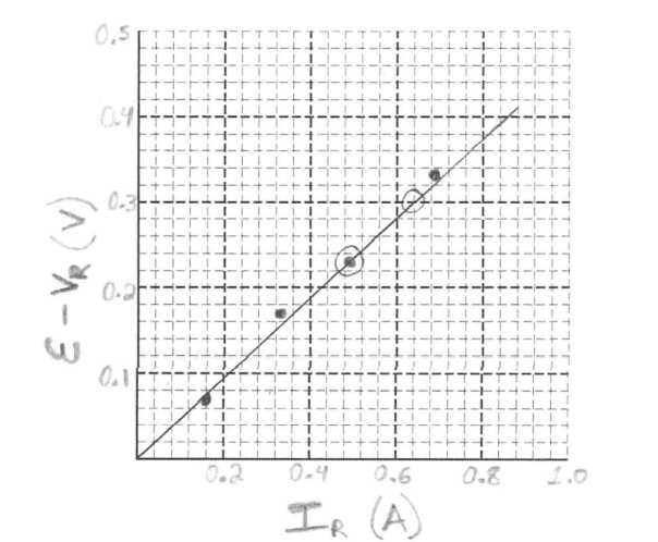
(e)
slope = \(\frac{0.3-0.23}{0.64-0.49}=\frac{0.07}{0.15}=0.4667\Omega = \frac{\varepsilon -V_{R}}{I_{R}} = r\)
(f)
\(r = \frac{\rho l}{A}\) \(\rho = \frac{r.A}{l}= \frac{(0.4667)\left ( \pi \cdot (1\times 10^{-3})^{2} \right )}{3}\)
\(\rho = 4.88 \times 10^{7}\Omega m\)
(g)
(g)
i. Suppose the ammeter used to collect these data was not ideal. Would the actual value of the resistance of the wire sample be greater than, less than, or equal to that calculated in part (e) ?
______Greater than ____√____Less than ________Equal to
If the ammeter was not ideal, it would have a resistance greater than zero, but we assumed all of the resistance from the wire came from the wire sample, so actually some of the resistance belongs to the ammeter, not completely to the wire sample.
ii. If the ideal voltmeter is replaced by a voltmeter that is not ideal and the experiment is repeated, would the readings of the ideal ammeter be greater than, less than, or equal to those in the data chart before part (c) ?
___√____Greater than ________Less than ________Equal to
A non-ideal voltmeter would decrease the resistance in the circuit (due to the parallel structure) so there would be more current drawn from the battery.