Definition of Current
- Current – The flow of charge through a conductor. In conductors, electrons move freely. When electrons move, charge moves around. Negative charge is due to excess electrons. Positive charge is due to a deficit of electrons.
- Current flows in a conductor when there is a potential different from one end of a conductor to another.
- The rate of current flow is defined as Current
$
\text { Current }=\frac{\text { charge }}{\text { time }}
$
$
\mathrm{I}=\frac{Q}{t}
$
*units: Amperes (A)
Direction of Current
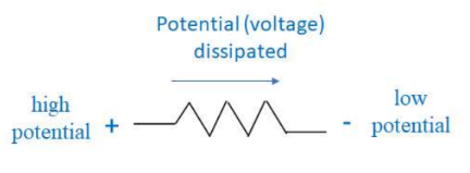
- Current flows down a “voltage hill”.
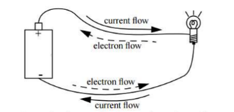
Current from high electrical potential (positive charge) to low electrical potential (negative charge). - In a solid conductor, current is due to the flow of free electrons. As electrons are negatively charged, they are attracted to flow towards positive charge. However, in circuit analysis, we pretend that current is due to the flow of positive charge in the opposite direction of electron movement. This is called conventional current.
- (Conventional) Current flows from positive charge to negative charge in a conductor.
+high potential -low potential
*Potential (measured in volts) is electric potential energy per unit charge.
- Charge flows from a source to a load in a circuit. A load is an object that uses electrical energy such as a motor or light. Charge arrives at a load with high energy and leaves with lower energy.
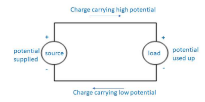
- Charge flows around a circuit repeatedly. Electrostatics will never move conventional current from a negative charge (lower potential) to positive charge (high potential).
*After leaving a source, current circulates to a load. The load consumes energy but not charge.
*Resistance of a theoretically perfect conductor is zero. *Resistance of a perfect inductor would be infinite.
Resistors are required in circuits to slow down current. Electrons moving too fast will cause a circuit to become very hot and can burn out circuit elements.
Ohm’s Law
Ohm’s Law relates the difference in potential(known as voltage) from one side of a load to another (V), the resistance of the load (R) and current ( I ).
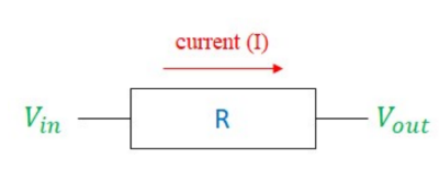
$\mathrm{I}$ – current though element $\Delta \mathrm{V}=V_{\text {out }}-\Delta V_{\text {in }}:$ potential difference across element (measured in Volts, V) $R$ – resistance through element
Series vs. Parallel
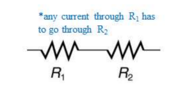
- When two elements are in series, they are connected end to end so that there is only one way for current to flow. When resistors are in series, current has to pass through both resistors.
${ }^* \mathrm{R}_{\mathrm{eq}}=$ Equivalent resistance.
In series, current adds.
$
R_{e q}=R_1+R_2
$
Current is the same in series. Voltage is shared between elements in series; elements with more resistance drop more voltage. Adding a resistor in series with another resistor will increase the equivalent resistance and decrease the current.
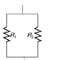
- Elements that are in parallel are on different paths, so current is divided between the elements. However, the potential in each path is the same. In parallel, reciprocals of the resistances add up.
In parallel, the reciprocals of resistances add.
$
\frac{1}{R_{e q}}=\frac{1}{R_1}+\frac{1}{R_2}
$
*Current splits. $\mathrm{R}_1$ and $\mathrm{R}_2$ share current
Voltage is the same in parallel. Current is split between the elements. More current will go down the path with less resistance. Adding a resistor in parallel with another resistor will decrease the equivalent resistance and increase the current in the circuit.
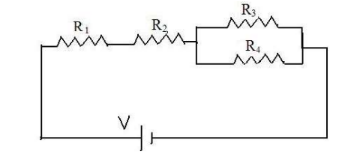
- In the circuit below, $\mathrm{R}_1$ and $\mathrm{R}_2$ are in series since current from the battery has to pass through both resistors. However, $R_3$ and $R_4$ are not in series since the current flowing through one is equal to the current in the other. After passes through $\mathrm{R}_2$, current can either take the path through $\mathrm{R}_3$ or the path through $\mathrm{R}_4$, making these two resistors in parallel. The majority of the current will go through the resistor with least resistance.
Apply Kirchoff’s Voltage Law to series circuits.
Kirchhoff’s Voltage (Loop) Law
In a closed loop, the vector sum of the potential differences across each
element is 0.
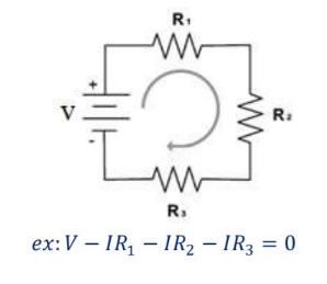
- Current flows from – to + in the source and + to – through the rest of the circuit. V across the source is positive and negative across the loads.
- Kirchhoff’s Voltage Law is consequence of conservation of energy.
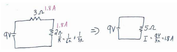
Example C: Appreciate the circuit on the right.
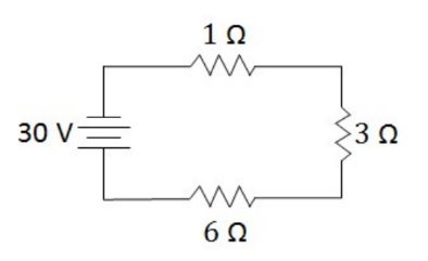
a) Find the current in the circuit.
b) Find the voltage drop across each resistor.
All 3 resistors are in series, so they all have the same current. The current is found by dividing the total voltage by the equivalent resistance. Once this current is found, it can be used to find the voltage across each resistor using Ohm’s Law.
Answer/Explanation
$
R_{e q}=6 r+3 n+1 n=10 \Omega
$
(a) $I=\frac{V}{R}=\frac{30 \mathrm{~V}}{10 \mathrm{n}}=3 \mathrm{~A}$
(b)
$
\begin{aligned}
& V_{i R}=(3 A)(i n)=\frac{3 V}{V} \\
& V_{6 n}=(3 A)(6 n)=\frac{18 \mathrm{~V}}{9 \mathrm{~V}} \\
& V_{3 n}=(3 A)(3 n)=
\end{aligned}
$
*The voltages (3V+18V+9V) add up the battery voltage of 30 V, satisfying Kirchoff’s Loop Law.
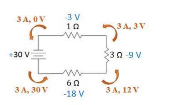
Circuit Analysis (Current leaves the long side of a battery) – The battery supplies $30 \mathrm{~V}$ to the current leaving it. When the current gets to the $6 \Omega$ resistor, it uses up $18 \mathrm{~V}$, leaving it with $12 \mathrm{~V}$. Current is never used up so it still have $3 \mathrm{~A}$. The current then loses $9 \mathrm{~V}$ in the $3 \Omega$ resistor, leaving it with $3 \mathrm{~V}$. The $1 \Omega$ uses up the remaining voltage, leaving the current with no potential.
*Whenever current goes back into the battery, it will not have any voltage left. All voltage must be used up in a circuit*
When the current goes back through the battery, it will gain the voltage back and the circuit will repeat. Batteries do eventually run out of potential over time. (a $9 \mathrm{~V}$ will eventually have $8 \mathrm{~V}$, then $7 \mathrm{~V}$,etc.)
*Voltage is potential difference. Therefore, the battery has positive voltage (since it adds voltage) and the resistors have negative voltage (since they take volts away).
Apply Kirchoff’s Current Law to parallel circuits.
Kirchhoff’s Current (Node) Law
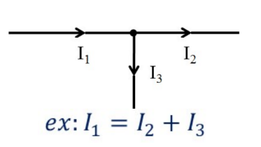
The sum of the current entering a node is equal to the sum of the current exiting a node.
- Kirchhoff’s Current Law is consequence of conservation of charge.
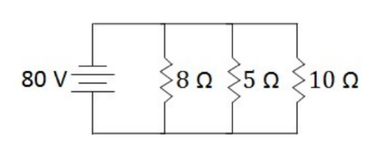
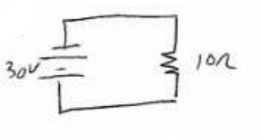
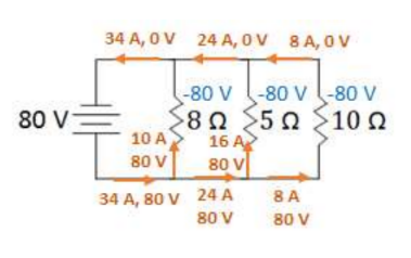
Example D: The circuit to the right has 3 elements in parallel.
(a) Find the current that leaves the battery.
(b) Find the current in each resistor.
Answer/Explanation
All 3 resistors are in parallel, so they all have the same potential (voltage). The total current can be found by dividing the battery voltage by the equivalent current. To find the current in each resistor, divide the battery voltage by each resistance since each resistor gets the full battery voltage.
(a) $\begin{aligned} \frac{1}{R_{e q}} & =\frac{1}{8 \Omega}+\frac{1}{5 n}+\frac{1}{10 n} \Rightarrow R_{e q}=2.35 \Omega \\ I & =\frac{V}{R}=\frac{80 \mathrm{~V}}{2.35 n}=34 \mathrm{~A}\end{aligned}$
(b) $\begin{aligned} & I_{82}=\frac{80 \mathrm{~V}}{8 \mathrm{~N}}=10 \mathrm{~A} \\ & I_{5 n}=\frac{80 \mathrm{~V}}{5 \mathrm{~N}}=16 \mathrm{~A} \\ & I_{10 \mathrm{~N}}=\frac{80 \mathrm{~V}}{10 \mathrm{~N}}=8 \mathrm{~A}\end{aligned}$
The currents (10A+16A+8A) add up to the total circuit current, satisfying Kirchoff’s Current Law.
Measure internal resistance.
Measuring Current – Ammeters have very low resistance and thus are connected in series with the element whose current is to be measured.
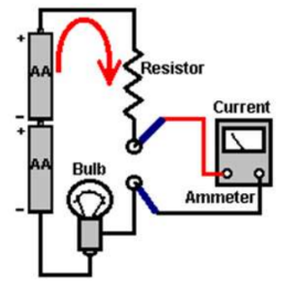
Since the ammeter is in series with the resistor, it will measure the same current as the resistor.
An ideal ammeter has a very small (negligible) resistance, so it will not drop any volts or alter the current and will therefore not affect the circuit by it being there.
*A non-ideal ammeter will have resistor, and therefore decrease the current lower than what it should be.
Measuring Voltage – Voltmeters have very high resistance and thus an accurate voltage reading would not be recorded if it was connected in series with the element with which current is to be measured. Thus, voltmeters are connected in parallel with the element that voltage is to be measured in.
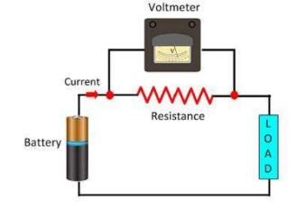
Since the voltmeter is in parallel with the resistor, it will measure the same voltage.
An ideal voltmeter has a very high (infinite) resistance, so only a negligible amount of current will flow through it.
Example A: Solve for each current in the circuit shown.
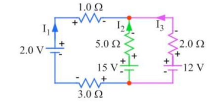
Answer/Explanation
There are 3 unknowns, so 3 equations need to be set up using Kirchoff’s laws using loops or nodes in the circuit.
Loop 1: $0=+2-I_1+5 I_2-15-3 I_1$ $\rightarrow-4 I_1+5 I_2=13$
*Since the loop goes “backwards” through $\mathrm{I}_2$, the conventional signs were reversed in the set-up for that section.
Loops 2: $0=+12-2 I_3+5 I_2-15$
$
\rightarrow 5 I_2-2 I_3=3
$
Node: $I_1+I_2+I_3=0$
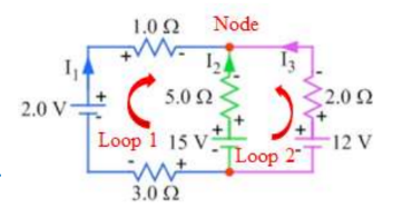
Solving the equations using a solver: $I_1=-2 A, I_2=1 A, I_3=1 \mathrm{~A}$ $* \mathrm{I}_1$ being negative means current flows opposite of the defined direction.
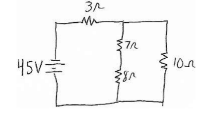
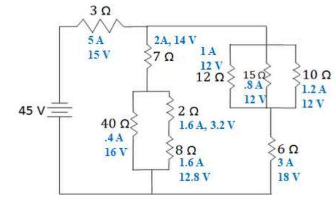
Example B: Solve the circuit shown.
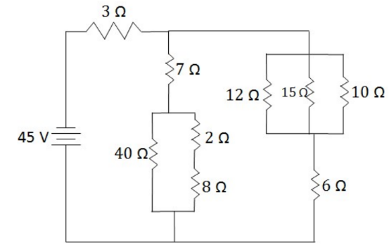
To solve a circuit (find the voltage and current across each element), find the equivalent circuit and then work backwards. The equivalent circuit is a circuit with one source and one resistor (that has
the equivalent resistance of the circuit. To find the equivalent, combine elements that are in series and parallel. You cannot do this in one step, so you need to combine things step by step.
Answer/Explanation
Step 1
-The $2 \Omega$ and $8 \Omega$ resistors combine in series $(2+8)$
-The $12 \Omega, 15 \Omega$, and $10 \Omega$ resistors combine in parallel $(1 /(1 / 12+1 / 15+1 / 10))$
Step 2
-The $40 \Omega$ and $10 \Omega$ resistors combine in parallel $(1 /(1 / 40+1 / 10))$
-The $4 \Omega$ and $6 \Omega$ resistors combine in series (4+6)
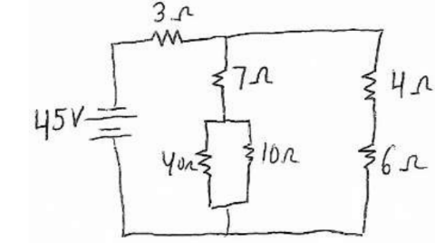
Step 3
-The 7Ω and 8Ω resistors combine in series (7+8)
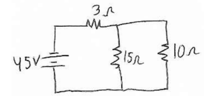
Step 4
-The 15Ω and 10Ω resistors combine in parallel (1/(1/15+1/10))
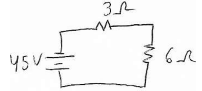
Step 5 (Equivalent Circuit)
-The 3Ω and 6Ω resistors combine in series
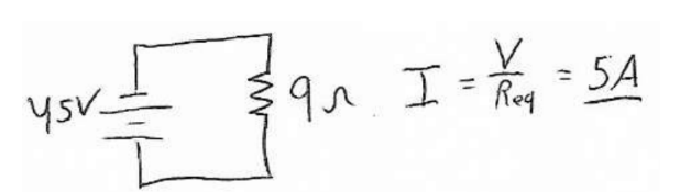
-The equivalent current is 9Ω
-The battery current is 5 A.

Much like Bilbo Baggins, we have to go there and back again, so we now go backwards through the steps to the original circuit. If items are in series when going backwards, they have the same current. If they are in parallel, they have the same voltage drop. We can then use ohm’s law to find the other quantity for each element.
Back to Step 4
-The $3 \Omega$ and $6 \Omega$ were in series so they both have the same current, $5 \mathrm{~A}$.
*The voltages are found using Ohm’s Law (V=IR). The calculated voltages $(30+15)$ add up to $45 \mathrm{~V}$, satisfying Kirchoff’s Loop Law.
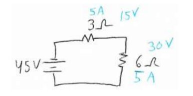
Back to Step 3
-The $6 \Omega$ resistor splits in parallel, so the two resistors have the same voltage, $30 \mathrm{~V}$.
*The current is found using Ohm’s Law ( $\mathrm{I}=\mathrm{V} / \mathrm{R})$. The calculate currents $(2+3)$ add up to $5 \mathrm{~A}$, satisfying Kirchoff’s Node Law.
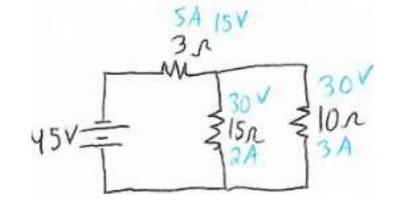
Back to Step 2
-The 15Ω resistor splits in series, so its current is the same for the 7Ω and 8Ω resistors it splits into.
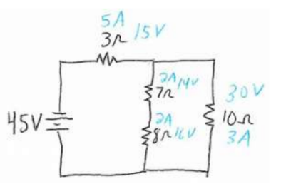
Back to Step 1
-The 8Ω resistor splits in parallel, so the two resistors have the same voltage, 16V, that the 8Ω resistor had.
– The 10Ω resistor splits in series, so its current is the same for the 4Ω and 6Ω resistors it splits into.
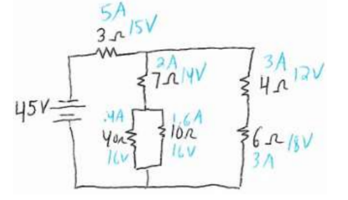
Back to Original Circuit (Answer)
-The 4Ω resistor splits in parallel, the resistors it splits into all have 12 V.
-The 10Ω resistor splits in series, so its current is kept for call elements.
Example B: Appreciate the circuit on the right.
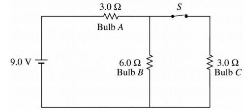
a) Calculate current in bulb A with the switch closed.
b) Which lightbulb is the brightest? Justify your answer.
c) Switch S is opened. Describe what happens to the brightness of each bulb.
Answer/Explanation
(a) The current through A is solved by finding the equivalent circuit and working backwards.
(b) A is the brightest bulb since it gets all the battery current. B and C have to split the current.
(c) If the switch is open:
- A gets dimmer. The equivalent resistance goes up, so the total current in the circuit goes down.
- B gets brighter. Even though the current in the circuit decreases, B now gets all the current instead of splitting it with C.
- C goes out since it is no longer part of the circuit.