Focus Question: How is Faraday’s law applied in the modern world?
An AC generator converts mechanical energy into electrical energy. Suppose a wire loop is made to rotate as shown on the right by some mechanical source:

As the loop rotates, the magnetic flux through the loop changes with time:
$
\begin{aligned}
& \phi=B A \cos (\omega t) \\
& * \omega=2 \pi f \text { (angular frequency) }
\end{aligned}
$
- The motional emf can be thus be found:
$
\begin{aligned}
& \varepsilon=\frac{-N \Delta \Phi}{\Delta t}=\frac{N d(B A \cos \omega t)}{d t} \\
& \varepsilon=N B A \omega \sin \omega t
\end{aligned}
$ - The emf is at a maximum when the plane of the loop is parallel to the magnetic field:
$\varepsilon_{P E A K}=\boldsymbol{\omega} \boldsymbol{N} \boldsymbol{B} \boldsymbol{A}$
Focus Question: What happens current runs through an inductor?
Inductance
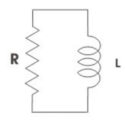
- Inductor – A component that stores energy temporarily in a magnetic field. Inductors resist changes in
current.
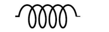
*usually created by coiling wire into many loops. More loops = stronger magnetic field Schematic symbol:
- In a circuit with an inductor, current doesn’t automatically jump to its max value, $I=\frac{\varepsilon}{R}$. As current increases, magnetic flux through the inductor increases with time, inducing an emf in the inductor; opposite the direction of the current.
- Self-Inductance – The circuit itself produces a changing magnetic flux and thus induces an emf due its own current.
$
\varepsilon_L=-N \frac{d \phi}{d t}
$
- Inductance – Property of inductor; ratio of magnetic flux to current flow.
$
\begin{aligned}
& L=N \frac{\phi}{I} \\
& L=-\frac{\varepsilon}{\frac{d I}{d t}} \rightarrow \varepsilon_L=-L \frac{d I}{d t}
\end{aligned}
$
L, inductance, is basically “electrical inertia”. The second equation above is comparable to $F=m \frac{d v}{d t}$. units of inductance: Henry (H); $1 \mathrm{H}=1 \mathrm{Vs} / \mathrm{A}$
*inductance can be thought of as resistance to change in current, not to current itself.
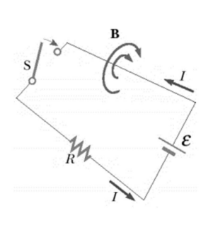
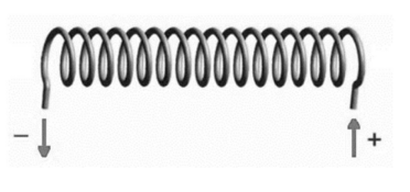
Example A: Consider the solenoid shown with current flowing in the indicated direction.
a) Find the direction of the self-induced emf when the current is increasing.
b) Find the direction of the self-induced emf when the current is decreasing.
Answer/Explanation
a) The current is to the left and increasing, the change in current is the left, inducing an emf to resist this change to the right. The solenoid acts as an inductor, which does not let current suddenly change, so the current will slowly start to flow to the left rather than jumping immediately when power is connect.b) The current is to the left, but decreasing, so the change in current is the right. The solenoid will resist this change by inducing an emf with a current to the left.
LR Circuits
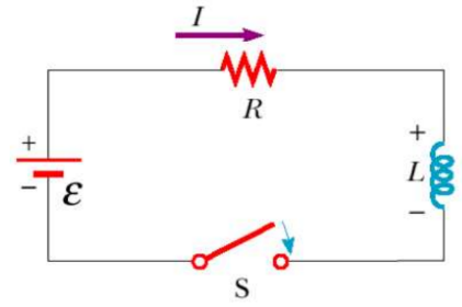
- RL Circuit – Contains a resistor and inductor in parallel.
- As the current increases towards its maximum value
(when switch is closed), an emf is induced in the inductor:
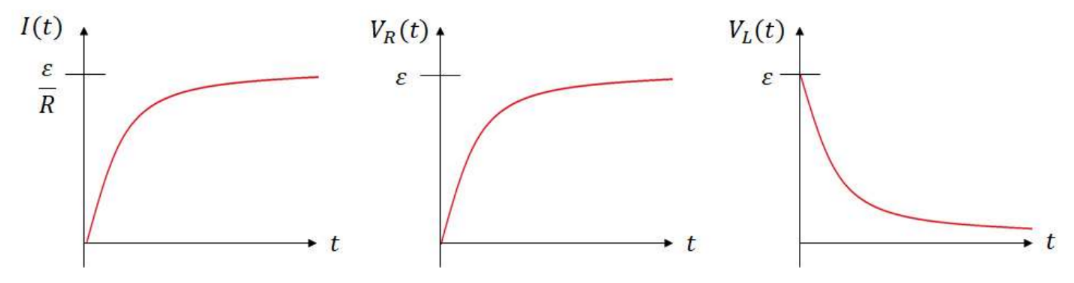
The inductor prevents the current from immediately jumping to $\varepsilon / R$. Instead the current will build to this value over time.
- Voltage across the resistor the resistor, $V_R(t)$, will start at zero, but will build to $\varepsilon$ over time.
- Voltage across the inductor, $V_L(t)$, will start at the battery value, $\varepsilon$, giving a back emf to prevent current. At steady state, this emf will drop to zero, and the inductor will act as normal current-carrying wire, but it will have energy stored in its magnetic field.
- Current, $I(t)$, will start at zero since the inductor doesn’t let current immediately jump when the battery is connected. Over time, it will build to $\varepsilon / R$ at steady state.
By Kirchoff’s Law:
$
\begin{aligned}
& \varepsilon-V_R-V_L=0 \\
& \rightarrow \varepsilon-I R-L \frac{d I}{d t}=0 \rightarrow \varepsilon-I R=L \frac{d I}{d t}
\end{aligned}
$
Multiplied both sides by $-1 / \mathrm{R}$ to get $\mathrm{I}$ by itself to make integration easier:
$
I-\frac{\varepsilon}{R}=-\frac{L}{R} \frac{d I}{d t}
$
Separate the variables:
$
\frac{d I}{I-\frac{\varepsilon}{R}}=-\frac{R}{L} d t
$
The current starts at 0 and goes to $I$ at some time, $t, I(t)$ :
$$
\begin{aligned}
& \int_0^{I(t)} \frac{d I}{I-\frac{\varepsilon}{R}}=\int_0^t-\frac{R}{L} d t \\
& \rightarrow \ln \left|I-\frac{\varepsilon}{R}\right| \begin{array}{c}
I(t) \\
0
\end{array}=-\frac{R}{L} t \rightarrow \ln \left|I(t)-\frac{\varepsilon}{R}\right|-\ln \left|-\frac{\varepsilon}{R}\right|=-\frac{R}{L} t \rightarrow=\ln \left|\frac{I(t)-\frac{\varepsilon}{R}}{-\frac{\varepsilon}{R}}\right|=-\frac{R}{L} t \\
& \rightarrow \frac{I(t)-\frac{\varepsilon}{R}}{-\frac{\varepsilon}{R}}=e^{-\frac{R}{L} t} \\
& I(t)=\frac{\varepsilon}{R}\left(1-e^{-\frac{R}{L} t}\right) \quad I(t)=\frac{\varepsilon}{R}\left(1-e^{-\frac{t}{\tau}}\right) \\
&
\end{aligned}
$
- The time constant for an LR is $\tau=\frac{L}{R}$.
- Using ohm’s law for the resistor, the voltage across the resistor is: $V_R(\boldsymbol{t})=\boldsymbol{\varepsilon}\left(\mathbf{1}-e^{-\frac{t}{\tau}}\right)$
- When the voltage is not dropped in the resistor, it is dropped in terms of back emf in the inductor:
$
V_L(t)=\varepsilon e^{-\frac{t}{\tau}}
$ - Charging circuit graphs:
- Discharging Circuit – Suppose switch 1 is open and switch 2 is closed at $\mathrm{t}=0$ after steady state conditions have been reached.
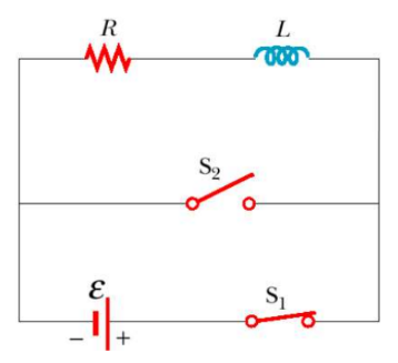
When the circuit is charged and disconnected, the energy stored in the inductor’s magnetic field acts a battery for the resistor. The current will continue flowing in the direction it was going (since the inductor resists the current decreasing) until the inductor runs out of emf.
By Kirchoff’s Law:
$
\begin{aligned}
& V_R+V_L=0 \\
& -I R-L \frac{d I}{d t}=0 \rightarrow I R=-L \frac{d I}{d t} \rightarrow I=-\frac{L}{R} \frac{d I}{d t} \\
& \rightarrow \frac{d I}{I}=-\frac{R}{L} d t
\end{aligned}
$
The current starts at $\frac{\varepsilon}{R}$ and decreases to some value, $\mathrm{I}(\mathrm{t})$ after time $\mathrm{t}$ :
$
\begin{aligned}
& \int_{\frac{\varepsilon}{R}}^{I(t)} \frac{d I}{I}=\int_0^t-\frac{R}{L} d t \\
& \rightarrow \ln |I| \underset{\frac{\varepsilon}{R}}{I(t)}=-\frac{R}{L} t \rightarrow \ln |I(t)|-\ln \left|\frac{\varepsilon}{R}\right|=-\frac{R}{L} t \rightarrow \ln \left|\frac{I(t)}{\frac{\varepsilon}{R}}\right|=-\frac{R}{L} t \\
& \rightarrow \frac{I(t)}{\varepsilon / R}=-\frac{R}{L} t
\end{aligned}
$
$I(t)=\frac{\varepsilon}{R}\left(1-e^{-\frac{R}{L} t}\right) \quad I(t)=\frac{\varepsilon}{R}\left(1-e^{-\frac{t}{\tau}}\right)$
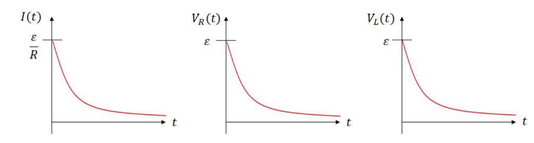
- By ohm’s law: $V_R(t)=\varepsilon e^{-\frac{t}{\tau}}$
- The inductor acts as the battery, so its emf drains with the circuit: $\boldsymbol{V}_{\boldsymbol{L}}(\boldsymbol{t})=\boldsymbol{\varepsilon} \boldsymbol{e}^{-\frac{\boldsymbol{t}}{\tau}}$
- Disharging circuit graphs:
Example D: Appreciate the circuit given on the right. Assume $\mathrm{V}=100 \mathrm{~V}, \mathrm{R}=20 \Omega$ and $\mathrm{L}=4.0 \mathrm{H}$.
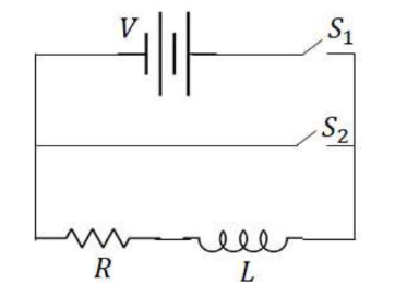
a) What is the current through resistor $\mathrm{R}$ right when the switch is closed?
b) What is the voltage across the inductor just after the switch is closed?
c) Find the potential across the inductor as a function of time.
d) At what rate is the energy stored in the inductor increasing at time $t=2 \mathrm{~s} .0$ ?
a) The current is zero initially, as the inductor will not allow the current to immediately jump to a value right when the power in connected.
b) The back emf is originally $\mathbf{1 0 0} \mathbf{V}$ against the direction of the current.
c) The time constant of the inductor is $\tau=\frac{L}{R}=\frac{4 H}{20 \Omega}=0.2$
$
V_L(t)=100 e^{-\frac{t}{2}} \rightarrow V_L(t)=\mathbf{1 0 0} \boldsymbol{e}^{-5 t}
$
d) The rate of change of energy is power.
$
P=\frac{d U}{d t}=\frac{d}{d t}\left(\frac{1}{2} L I^2\right)=L I \frac{d I}{d t}
$
The current as a function of time is given by: $I(t)=\frac{100 \mathrm{~V}}{20 \Omega}\left(1-e^{-5 t}\right)=5\left(1-e^{-5 t}\right)$
$
\begin{aligned}
& \frac{d I}{d t}=25 e^{-5 t} \\
& \rightarrow P=L I \frac{d I}{d t}=(4 H)\left(5\left(1-e^{-5(2)}\right)\left(25 e^{-5(2)}\right)=.02 \mathrm{~W}\right.
\end{aligned}
$
Example E: A L $=5.0$ Henry inductor carrying an initial current of $100 \mathrm{~A}$ is discharged through a resistor of $\mathrm{R}=1.0 \Omega$.
a) Find the voltage drop across the resistor as a function of time.
b) Find the time needed for the current to reach $10 \mathrm{~A}$.
$
\begin{aligned}
& \text { a) } V_R(t)=I R e^{-\frac{R}{L} t} \rightarrow V_R(t)=(100 A)(1 \Omega) e^{-\frac{1 \Omega}{5 H} t} \\
& \rightarrow V_R(t)=100 e^{-.2 t} \\
& \text { b) } I(t)=I_0 e^{-\frac{R}{L} t} \rightarrow I(t)=100 e^{-\frac{1}{5} t} \\
& \rightarrow 10=100 e^{-.2 t} \rightarrow .1=e^{-.2 t} \rightarrow \ln |.1|=-.2 t \\
& \rightarrow t=\frac{\ln |.1|}{-.2}=11.5 \mathrm{~s}
\end{aligned}
$
Example F: The circuit on the right is allowed to reach a steady state. At time $\mathrm{t}=0$, the switch is closed.
a) What is the potential across the inductor at $\mathrm{t}=0$ ?
b) At what rate is the current increasing in the inductor at $\mathrm{t}=0$ ?
c) How much current flows through the inductor after the switch has been closed for a long time?
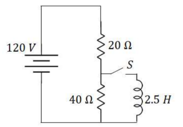
a) The inductor is in parallel with the $40 \Omega$ resistor, so it only produces a back emf to match the voltage across the $40 \Omega$ resistor at steady state.
$
V_L=\frac{40}{20+40}(120 \mathrm{~V}) 80 \mathrm{~V}
$
$
\begin{aligned}
& \text { b) } \varepsilon=-L \frac{d I}{d t} \rightarrow \frac{d I}{d t}=-\frac{\varepsilon}{L} \\
& \rightarrow \frac{d I}{d t}=\frac{80 \mathrm{~V}}{2.5 H}=32 \frac{A}{s}
\end{aligned}
$
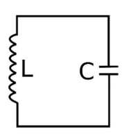
The LC Circuit
- LC Circuit – Contains a charged capacitor and inductor (with little resistance).
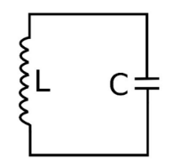
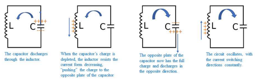
If a fully charged capacitor is connected to an inductor, it will discharge through the inductor. When the capacitor runs out of charge to discharge through the inductor, the inductor will produce an induced current to stop the current from decreasing, sending charge to the other plate of the conductor. The opposite plate eventually becomes fully charged, and then discharges again through the inductor, which does its thing again. The LC oscillates as a result.
$\begin{aligned} & \text { By Kirchoff’s Law: } V_C+V_L=0 \\ & \rightarrow \frac{q}{C}+L \frac{d i}{d t}=0 \\ & \text { Since } i=\frac{d q}{d t}, \frac{d i}{d t}=\frac{d^2 q}{d t^2} \\ & \rightarrow \frac{q}{C}+L \frac{d^2 q}{d t^2}=0 \\ & \rightarrow \frac{d^2 q}{d t^2}+\frac{1}{L C} q=0\end{aligned}$
The energy above matches the equation for simple harmonic motion from AP Physics C: Mechanics:
$
\left(\frac{d^2 x}{d t^2}+\omega^2 x=0\right)
$
In this case, the variable is the charge over time and the angular frequency is $\omega=\sqrt{\frac{1}{L C}}$.
- The period of an RC circuit is $T=\frac{2 \pi}{\omega}=\frac{2 \pi}{\sqrt{\frac{1}{L C}}} \rightarrow \boldsymbol{T}=\mathbf{2} \pi \sqrt{\boldsymbol{L C}}$
- The total energy in an LC circuit is $E=\frac{1}{2} L I^2+\frac{1}{2} C V_C^2$
- From the general solution to the differential equation, the charge over time can be given by:
$
Q(t)=Q_0 \cos (\omega t) \rightarrow Q(t)=Q_0 \cos \left(\frac{1}{\sqrt{L C}} t\right)
$