Focus Question: How does a capacitor store electric potential energy?
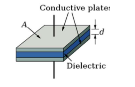
- A capactior is formed by two conductors seperated by an insulator. When a capacitor is connected to a battery, it quickly becomes charged, with the two plates taking on opposite charges. The net charge on a capacitor is zero since the plates have equal but opposite charges.
- Function of a capacitor – Stores electrical energy in the electric field between two plates.
- An electric field exists between the two conductors in a capacitor. The field and electric potential difference are proportional to the charge on the conductors.
$
C=\frac{Q}{V}
$
$Q$ – charge on each plate
V – potential difference units: Farads $(F)$
*A capactior always have zero net charge as the plates have equal but opposite charges. The charge in the equation for capacitance is the charge of each plate.
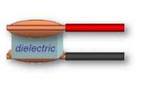
- Capacitor symbol:
Parallel Plate Capacitors
- Gauss’s Law can be used to find the electric field between the plates of the capacitor:
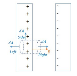
$\begin{aligned} & \emptyset=\oint \vec{E} \cdot \overrightarrow{d A}=\frac{Q_{e n c}}{\epsilon_0} \rightarrow E A=\frac{\sigma A}{\varepsilon_0} \\ & \rightarrow E=\frac{\sigma}{\varepsilon_0}\end{aligned}$
Relating E to other variabes: $V=E d \rightarrow \frac{Q}{C}=E d \rightarrow C=\frac{Q}{E d}$
$
\rightarrow C=\frac{Q}{\frac{\sigma}{\varepsilon_0} d} \rightarrow C=\frac{Q \varepsilon_0}{\frac{Q}{A} d} \rightarrow C=\varepsilon_0 \frac{A}{d}
$
Capacitors in Parallel
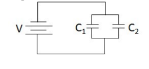
The capacitors are in parallel, so they have the same voltages, $V_1=V_2=V$. The charges add, $Q_{e q}=Q_1+Q_2$.
$
C_{e q} \forall=Q_1 \forall+Q_2 \forall
$
Capacitors in parallel act like a single capacitor whose capacitance is the sum of the capacitances.
$C_{e q}=C_1+C_2$
Capacitors in Series
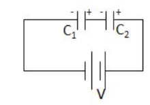
In series, a negative charge flows to $\mathrm{C}_1$ and a positive charge flows to $\mathrm{C}_2$. The region between the capacitors will remain neutral. In series, each capacitor stores the same amount of charge.
The voltages add: $V_{e q}=V_1+V_2 \rightarrow \frac{\theta}{C_{e q}}=\frac{\theta}{C_1}+\frac{Q}{C_2}$
Finding the equivalent capacitance of capacitors in series works the same as finding the equivalent resistance of resistors in parallel.
$\frac{1}{C_{e q}}=\frac{1}{C_1}+\frac{1}{C_2}$
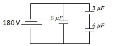
Example C: Ponder the circuit on the right:
a) What is the equivalent capacitance of the network?
b) What is the potential difference across the 3 μF capacitor?
c) How much charge is stored in the 6 μF capacitor?
To find the equivalent capacitance, the equivalent circuit needs to be found:
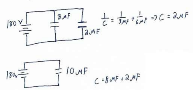
Answer/Explanation
a)10 μF
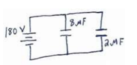
(b) In step 2 of the finding the equivalent circle, the charge on the $2 \mu F$ is the same as the charge on both the $3 \mu F$ and $6 \mu F$ capacitors since they are in series.
$
Q=C V=\left(2 \times 10^{-6} \mathrm{~F}\right)(180 \mathrm{~V})=3.6 \times 10^{-4} \mathrm{C}
$
The $3 \mu F$ capacitor thus has a charge of $3.6 \times 10^{-4} C$ stored:
$
V=\frac{Q}{C}=\frac{3.6 \times 10^{-4} C}{3 \times 10^{-6} \mathrm{~F}}=\mathbf{1 2 0} \mathrm{V}
$
(c) Since the $3 \mu F$ capacitor has $120 \mathrm{~V}$ across it, the $6 \mu F$ capacitor has $60 \mathrm{~V}$ across it since they must add to 180
$\mathrm{V}$.
$
U=\frac{1}{2} C V^2=\frac{1}{2}\left(6 \times 10^{-6} \mathrm{~F}\right)(60 \mathrm{~V})^2=.011 \mathrm{~J}
$
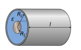
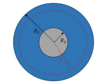
Example D: Find the capacitance of two concentric conducting cylinders of length $1.0 \mathrm{~m}$. The inner cylinder has radius $1.0 \mathrm{~mm}$ and the outer cyilnder has radius 2.0 $\mathrm{mm}$. The capacitors have equal but opposite charges of linear charge density $\lambda$. Cylindrical capatiors are much more common than parallel plate capacitors. To find the capacitance of a cylindrical capacitor using $\mathrm{C}=\mathrm{Q} / \mathrm{V}$, the voltage needs to be found based on the field.
Answer/Explanation
Step 1: Found field in the region between the plates using Gauss’s Law.
\begin{aligned}
& \emptyset=\oint \vec{E} \cdot \overrightarrow{d A}=\frac{Q_{e n c}}{\varepsilon_0} \\
& E(2 \pi r t)=\frac{\lambda t}{\varepsilon_0} \\
& \rightarrow E=\frac{\lambda}{2 \pi r \varepsilon_0}
\end{aligned}
Step 2: Find the potential using $V=-\int E \cdot d r$. The potential will be found based on going from the inner to outer plate.
$
\begin{aligned}
& V=-\int_{R_1}^{R_2} \frac{\lambda}{2 \pi r \varepsilon_0}=-\left(\frac{\lambda}{2 \pi \varepsilon_0} \ln |r|\right)\left|R_{R_1}^{R_2}=-\frac{\lambda}{2 \pi \varepsilon_0}\left(\ln \left|R_2\right|-\ln \left|R_1\right|\right)=-\frac{\lambda}{2 \pi \varepsilon_0} \ln \right| \frac{R_2}{R_1} \mid \\
& \rightarrow V=\frac{\lambda}{2 \pi \varepsilon_0} \ln \left|\frac{R_1}{R_2}\right|
\end{aligned}
$
Step 3: Find the capacitance using $\mathrm{C}=\mathrm{Q} / \mathrm{C}$
$
\begin{aligned}
& C=\frac{A L}{\frac{A}{2 \pi \varepsilon_0} \ln \left|\frac{R_1}{R_2}\right|} \\
& \rightarrow C=\frac{2 \pi \varepsilon_0 L}{\ln \left|\frac{R_1}{R_2}\right|}
\end{aligned}
$
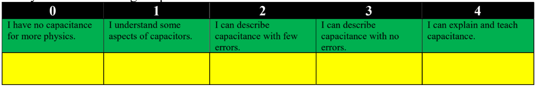
Rate your understanding: Capacitors
- Most capacitors have a solid, nonconducting material between the plates. This material is called a dielectric.
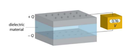
- Function of a dielectric:
- Keeps plates close, but not in contact
- Can tolerate greater field without dielectric breakdown
*Air is more suspect to dielectric breakdown, in which the insulator ionizes and charge can flow between the plates.
- Increases capacitance.
The potential difference between two charge plates decreases when a dielectric is used, but the charge on each plate stays the same. Electric field decreases when a dielectric is inserted, due to small induced charges appearing on the surfaces of the dielectric.
- The dielectric constant, κ:
$\kappa=\frac{C}{C_0}$
C-Capacitance with dielectric
$\mathrm{C}_0$ – Capacitance without dielectric $*_\kappa \geq 1$
Field Decreases: $\kappa=\frac{V_0}{V}=\frac{E_0 d}{E d}=\frac{E_0}{E}$
Permittivity increases: $\varepsilon=\kappa \varepsilon_0$
Voltage:
Case 1: If the battery is no longer connected, voltage decreases $\kappa=\frac{Q / V}{Q / V_0}=\frac{V_0}{V}$ *in this case, energy decreases due to the work done to insert dielectric.
Case 2: If the capacitor is still connected to the battery, voltage remains constant *In this case, energy increases since capacitor increases and voltage is constant.
- Electric field in a dielectric using Gauss’ Law:
*induced charges appear on the surface of the dielectric.
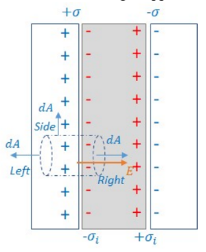
$\sigma:$ charge on plates $\quad \sigma_i:$ induced charge on dielectric surface
$
\begin{aligned}
& \emptyset=\oint \vec{E} \cdot \overrightarrow{d A}=\frac{Q_{e n c}}{\epsilon_0} \rightarrow E A=\frac{\left(\sigma-\sigma_i\right) A}{\varepsilon_0} \\
& \rightarrow E=\frac{\sigma-\sigma_i}{\varepsilon_0}
\end{aligned}
$
* Since the permittivity increases by a factor of $\kappa, \mathrm{E}$ is also $E=\frac{\sigma}{\kappa \varepsilon_0}$
Relationship between induced dielectric charge and dielectric constant:
$
\begin{aligned}
& \frac{\sigma-\sigma_i}{\varepsilon_{\forall}}=\frac{\sigma}{\kappa \varepsilon_\theta} \\
& \rightarrow \boldsymbol{\kappa}=\frac{\boldsymbol{\sigma}}{\boldsymbol{\sigma}-\boldsymbol{\sigma}_{\boldsymbol{i}}}
\end{aligned}
$
$\kappa=\frac{E_0}{E}$
- Energy density in dielectric
Density $=\frac{U}{\text { Volume }}=\frac{\frac{1}{2} \kappa C V^2}{A d}=\frac{\frac{1}{2} \kappa \varepsilon_0 \frac{A}{d} E^2 d^2}{A d}=\frac{1}{2} \kappa \varepsilon_0 E^2$
Example C: A capacitor having no dielectric has a capacitance of C. It is charged up to V by momentarily attaching it to a battery, and then disconnecting it.
a) What is the energy stored in the capacitor at this voltage?
b) What is the charge on the capacitor?
c) A dielectric having a permittivity of 20 is now carefully inserted between the plates of the capacitor.
What is its new capacitance?
d) What is the charge on the new capacitor?
e) What is the energy stored in the new capacitor?
f) Explain the discrepancy between (e) and (a).
Answer/Explanation
a) $U=\frac{1}{2} C V^2$
b) $Q=C V$
c) $\kappa=\frac{C^{\prime}}{C} \rightarrow C^{\prime}=\kappa C$
d) $Q=C^{\prime} V=\kappa C V$
*Inserting a dielectric increases the charge by a factor of kappa: $\kappa=\frac{Q}{Q_0}$
e) $U=\frac{1}{2} \frac{Q^2}{C}$ The charge and the capacitance both increase by a factor of the dielectric constant: $U=\frac{1}{2} \frac{(\kappa C V)^2}{\kappa C}=\frac{1}{2} \kappa C V^2$
f) The energy increased by a factor of the dielectric constant even though the circuit was not connected to power. The work done to insert the dielectric was converted to energy stored in the capacitor.
Rate your understanding: Dielectrics