Question
(a) Alternating current (a.c.) is converted into direct current (d.c.) using a full-wave rectification circuit. Part of the diagram of this circuit is shown in Fig. 7.1.
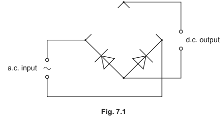
(i) Complete the circuit in Fig. 7.1 by adding the necessary components in the gaps.
(ii) On Fig. 7.1 mark with a + the positive output terminal of the rectifier.
(b) The output voltage V of an a.c. power supply varies sinusoidally with time t as shown in Fig. 7.2.
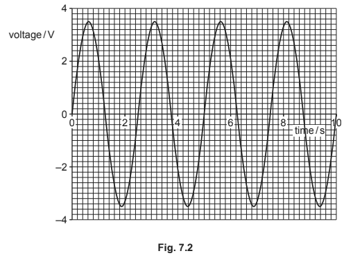
(i) Determine the equation for V in terms of t, where V is in volts and t is in seconds.
(ii) The supply is connected to a \(12\) Ω resistor. Calculate the mean power dissipated in the resistor.
Answer/Explanation
Ans:
(a) (i) two diodes added in correct directions (Both diodes pointing inwards and upwards), correct symbols only
(ii) ‘+’ anywhere on upper output wire
(b) (i) \(ω\) = \(2π / T\)
= \(2π / 2.5\)
= \(0.80 π\) or \(4 π / 5\) or \(2.5\)
\((V =)\) \(3.5 \sin (0.8 π t)\) or \(3.5 \sin (4 π t / 5)\) or \(3.5 \sin (2.5 t)\)
(ii) \((P =) \frac{V^{2}}{2R}\) or \((P=) \frac{V_{r.m.s^{2}}}{R}\)
= \(\frac{3.5^{2}}{2\times 12}\) or \(\frac{2.47^{2}}{12}\)
Question
An analogue signal is to be transmitted to a receiver. Before transmission, the signal passes through an analogue-to-digital converter (ADC). After transmission it passes through a digital-to-analogue converter (DAC) before finally reaching the receiver, as shown in Fig. 5.1.
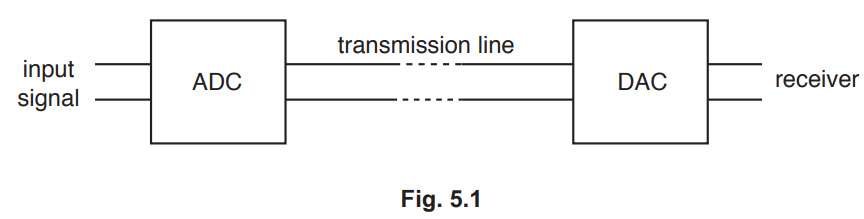
(a) State two advantages of converting the signal into digital form for transmission.
1.
2. [2]
(b) The variation with time of the potential difference (p.d.) of the input signal is shown in Fig. 5.2.
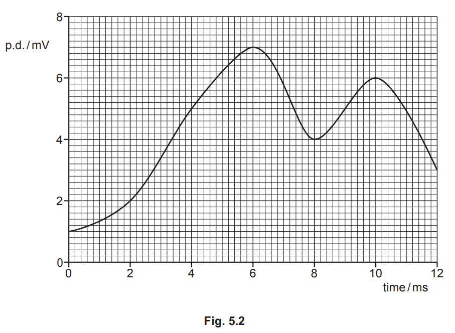
The ADC has a sampling frequency of 250Hz and uses 4-bit sampling, with the least significant bit corresponding to 1mV. The signal is first sampled at time 0, when the sampled bits are 0001.
(i) State the sampled bits at time 4ms and time 8ms.
4ms: ……………………………………… 8ms: ……………………………………… [1]
(ii) Part of the signal received by the receiver, after the sampled signal has passed through the DAC, is shown in Fig. 5.3.
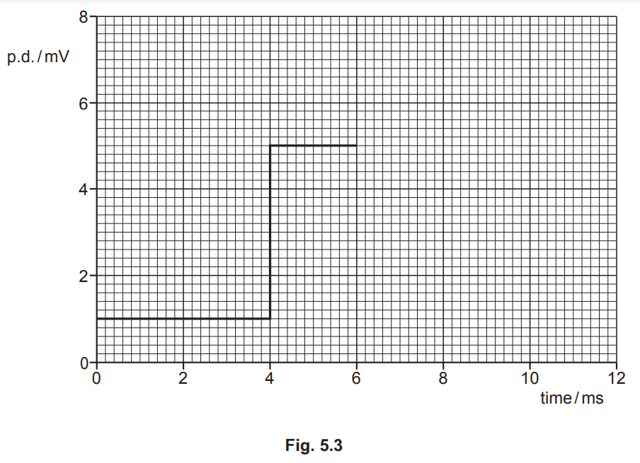
On Fig. 5.3, complete the line to show the received signal for time 0 to time 12ms. [2]
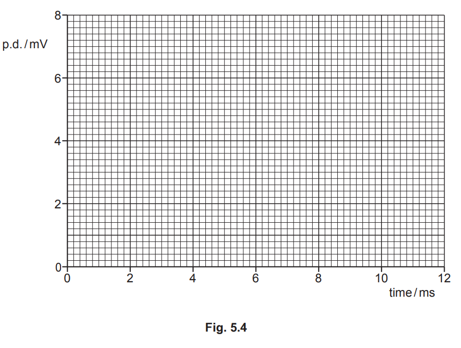
(c) The ADC in (b) is replaced with one that has a sampling frequency of 500Hz and uses 3-bit sampling, with the least significant bit corresponding to 2mV. On Fig. 5.4, sketch the signal that is now received, after passing through the DAC, from time 0 to time 12ms. [3]
Answer/Explanation
Ans
(a) • noise can be removed/signal can be regenerated
• extra bits can be added for error-checking
• signal can be encrypted (for increased security)
• data compression/multiplexing is possible
(b) (i) 4ms: 0101 and 8ms: 0100
(b) (ii) sketch: horizontal line continues to 8ms, then new horizontal line from 8ms to 12ms
level of line after 8ms is 4 mV
(c) sketch: series of steps of width 2ms
step heights at 0, 2, 4, 6, 4, 6 mV