MOVING CHARGES AND MAGNETISM
OERSTED EXPERIMENT
In 1802 Gian Domenico Romagnosi, an Italian lawyer and judge, found that a steady electric current flowing in wire affected a magnetic needle placed near it. He published his observation in a local newspaper (called Gazzetta di Trentino). But nobody noticed this phenomenon.
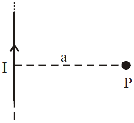
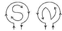
In 1820 Hans Christian Oersted (a Danish Physicist) rediscovered this phenomenon. He noted that a magnetic compass needle, brought close to a straight wire carrying a steady electric current, aligned itself perpendicular to the wire i.e., the direction of magnetic field is tangential to a circle which has the wire as centre, and which has its plane perpendicular to the wire (Fig 1-a).
Oersted also noticed that on reversing the direction of current; the direction of magnetic field is reversed.
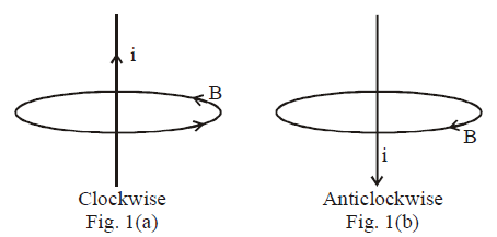
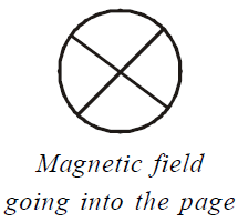
In first case when current is in upward direction, magnetic field is clockwise (Fig 1-a) and when the current is downward, magnetic field is anticlockwise (Fig. 1-b).
MAGNETIC FIELD
It is a region of space around a magnet or current carrying conductor or a moving charge in which its magnetic effect can be felt.
The conductor carrying current is electrically neutral but a magnetic field is associated with it.
The SI unit of magnetic field induction is tesla (T) or weber/m2 and cgs unit is gauss. 1 gauss = 10–4 T
Comparison between electric field and magnetic field

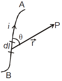
MAGNETIC FIELD DUE TO CURRENT CARRYING CONDUCTOR, BIOT-SAVART’S LAW
The magnetic induction  at any point outside the current path due to a small current element of length
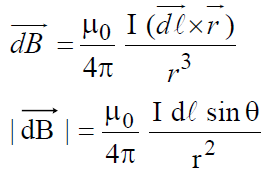
  (in the direction of the current) is given by Biot-Savart’s law
Also, 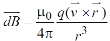 where
where is the drift velocity of charge
wherewhere μ0 = 4π × 10–7 TmA–1.
Direction of
The direction of is perpendicular to both  and
and  , governed by the right hand thumb rule of the cross-product of and .
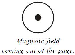
The magnetic fields going into the page and coming out of the page are represented as follows :
MAGNETIC FIELD DUE TO VARIOUS CURRENT CARRYING CONDUCTORS
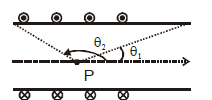
MAGNETIC FIELD DUE TO FINITE SIZED CONDUCTOR
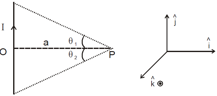
ELUCIDATION

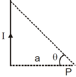
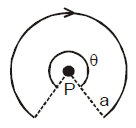
MAGNETIC FIELD NEAR THE END OF A FINITE SIZED CONDUCTOR
MAGNETIC FIELD DUE TO AN INFINITELY LONG CONDUCTOR
ELUCIDATION
Magnetic field in the case of infinitely long wire
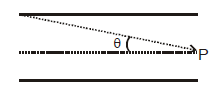
MAGNETIC FIELD NEAR THE END OF A LONG CONDUCTOR
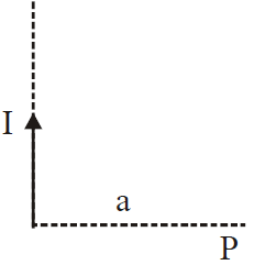
ELUCIDATION
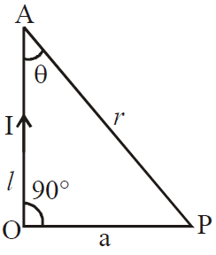
r = a cosec θ, l = a cot θ,
dl = a cosec2θ dθ

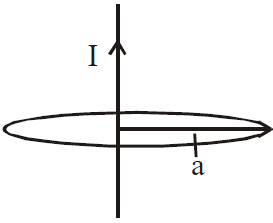
MAGNETIC FIELD DUE TO A CURRENT CARRYING COIL
MAGNETIC FIELD AT A POINT ON THE AXIS OF SYMMETRY OF A CIRCULAR COIL, AT A DISTANCE “X” FROM ITS CENTRE
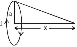
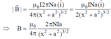
B = μ0NI a2/2(a2 + x2)3/2
or, 
N = total number of turns
a = coil radius
The direction of  is given by Right hand screw rule.
Right hand screw rule : If direction of rotation of right handed screw-head is the direction of current in a circular conductor then the direction of its advance is the direction of magnetic field. This is applicable even if the current, magnetic field are interchanged, as in case of current flowing through a straight conductor.
ELUCIDATION
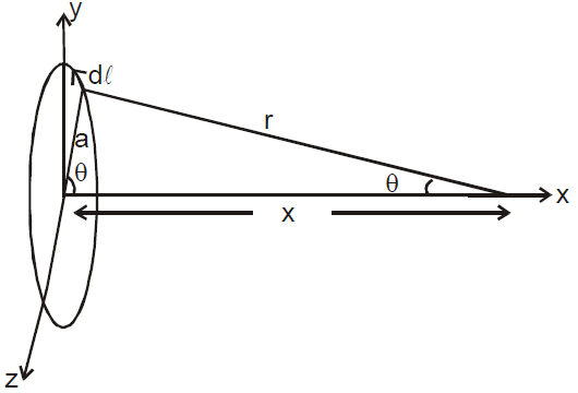
Let for a particular angle, position of small length element dl is given by its coordinates as
Now,  ,
,
Also we have .
.
Now  at any instant
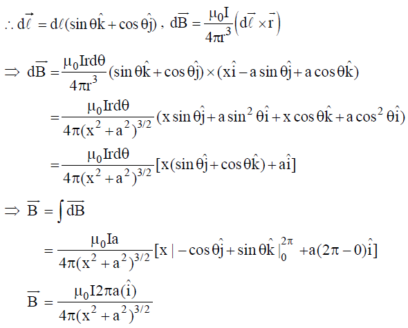 ,
,
If number of turns of coil are N, then
MAGNETIC FIELD AT THE CENTRE OF A CIRCULAR COIL
B = μ0NI / 2a 
MAGNETIC FIELD AT THE CENTRE OF A CIRCULAR ARC CARRYING CURRENT
where θ is in radian.
In this case the direction of magnetic field is into the page.
MAGNETIC FIELD INSIDE A CURRENT CARRYING SOLENOID
- Finite size solenoid
- Near the end of a finite solenoid
- In the middle of a very long solenoid, B = μ0 n I
- Near the end of a very long solenoid
n is the number of turns per unit length of solenoid.
- Magnetic field in the endless solenoid (toroid) is same throughout and is μ0nI.
- Magnetic field outside a solenoid or toroid is zero.
AMPERE’S CIRCUITAL LAW
The line integral of magnetic field across a closed loop is equal to 40 times the net correct inside the loop
i.e. 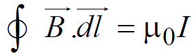
where I is the net current inside the loop.
- The direction of the magnetic field at a point on one side of a conductor of any shape is equal in magnitude but opposite in direction of the field at an equidistant point on the other side of the conductor.
- If the magnetic field at a point due to a conductor of any shape is Bo if it is placed in vacuum then the magnetic field at the same point in a medium of relative permeability μr is given by
 .
. - If the distance between the point and an infinitely long conductor is decreased (or increased) by K-times then the magnetic field at the point increases (or decreases) by K-times.
- The magnetic field at the centre of a circular coil of radius smaller than other similar coil with greater radius is more than that of the latter.
- For two circular coils of radii R1 and R2 having same current and same number of turns,
 where B1 and B2 are the magnetic fields at their centres.
 - The magnetic field at a point outside a thick straight wire carrying current is inversely proportional to the distance but magnetic field at a point inside the wire is directly proportional to the distance.
KEEP IN MEMORY
- If in a coil the current is clockwise, it acts as a South-pole. If the current is anticlockwise, it acts as North-pole.
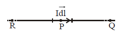
- No magnetic field occurs at point P, Q and R due to a thin current element
 .
.
- Magnetic field intensity in a thick current carrying conductor at any point x is
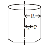
- Graph of magnetic field B versus x
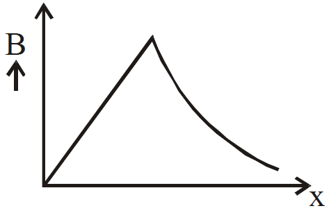
- Magnetic field is zero at all points inside a current carrying hollow conductor.
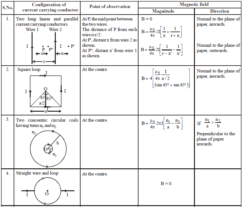
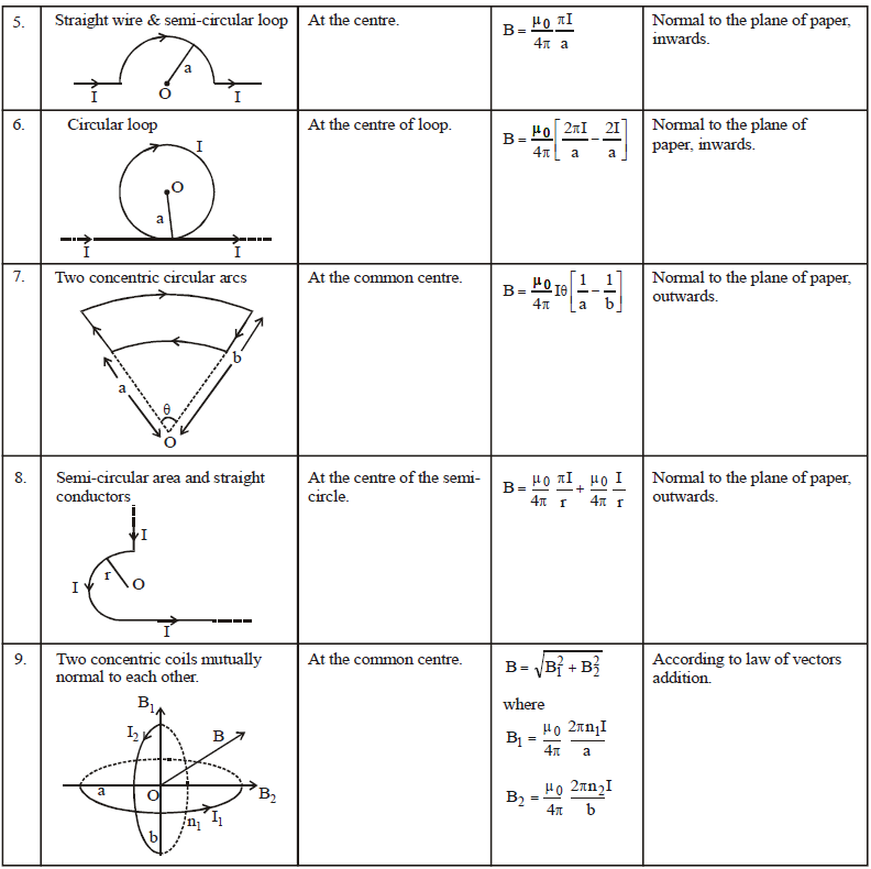
MAGNITUDE AND DIRECTION OF MAGNETIC FIELD DUE TO DIFFERENT CONFIGURATION OF CURRENT CARRYING CONDUCTOR
FORCE ON A CONDUCTOR
The force on a conductor is given by
F = BIl sin α
where,
where,
l is the length of the conductor in meter;
B is the flux density of field in tesla (Wb/m2);
I is the current in ampere and
α is the angle which the conductor makes with the direction of the field.
α is the angle which the conductor makes with the direction of the field.
Special case :
If α = 90°, then F = BIl
The direction of the force is given by Fleming’s left hand rule.
TORQUE ON A COIL
The torque acting on a rectangular coil placed with its plane parallel to a uniform magnetic field of flux density B is given by
τ = BINA
where N is the number of turns in the coil, A is the area and I is the current.
If the plane of the coil makes an angle α with the direction of the field, then
τ = BINA cos α
FORCE ACTING ON A CHARGED PARTICLE MOVING IN A UNIFORM MAGNETIC FIELD
The force acting on a particle having a charge q and moving with velocity in a uniform magnetic field \(\vec B\) is given by
where θ is the angle between \(\vec v\) and \(\vec B\)
Case (i)
If θ = 0, F = 0. Also if θ = 180°, F = 0
If a charged particle enters a uniform magnetic field in the direction of magnetic field or in the opposite direction of magnetic field, the force acting on the charged particle is zero.
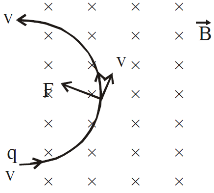
Case (ii)
If θ = 90°, F = qvB
In this case the force acting on the particle is maximum and this force acts as centripetal force which makes the charged particle move in a circular path.
where r is the radius of the circular path.
It is important to note that this force cannot change the speed of the charged particle and hence its kinetic energy. But it changes the velocity of charged particle (due to change in direction) and hence also causes a change in momentum. Also the work done by the force is zero as the force is acting perpendicular to the direction of motion.
Case (iii)
If θ = α is any other angle then the path taken is helical. The velocity of the charged particle can be split into two parts for better understanding.
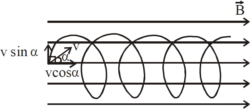
v cos α : The force on charged particle due to this component is zero. This component is responsible in moving the charged particle uniformly in the direction of .
v sin α : The force acting on charged particle due to this component is
This acts as the centripetal force and moves the particle in a circular path.
The combined effect of these two is a helical path.
A charged particle entering a uniform magnetic field at an angle executes helical path.
Radius of the helix, 
Angular frequency of rotation, 
Pitch of the helix = 
Direction of force  :We can use the rule of cross product. The direction of
  is perpendicular to the plane containing
  and and
  can be found by right hand thumb rule. It is important to note that if q is positive, we will get the correct direction of
  by right hand thumb rule. But if q is negative, we have to reverse the direction of force.
FLEMING’S LEFT HAND RULE
It states that if the fore finger, the central finger and the thumb of the left hand are stretched at right angles to each other then if the central finger represents the direction of current and fore finger represents field, the thumb will represent the direction of motion or force experienced by the current carrying conductor.
FORCE BETWEEN TWO PARALLEL CURRENTS
When a current flows in a conductor, the free charges (electrons in case of a metal wire) move. Each free charge movement generates a force which adds up to give the force on the conductor.
Force between infinitely long conductors placed parallel to each other at distance d.
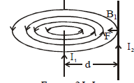
Force per unit length =
where l is the length of wire.
If currents are pointing in same direction, the force is of attractive nature and if currents are oppositely directed the force is of repulsive nature.
LORENTZ FORCE EQUATION
For a charged particle q moving in a region of simultaneously applied electric field  and magnetic field , the force experienced by it is given by
Torque on a current loop in uniform magnetic field is given by  where
where  is the magnetic moment of coil.
KEEP IN MEMORY
- No force acts on a charged particle if it enters a magnetic field in a direction parallel or antiparallel to the field.
- A finite force acts on a charged particle if it enters a uniform magnetic field in a direction with finite angle with the field.
- If two charged particles of masses m1and m2 and charges q1 and q2 are projected in a uniform magnetic field with same constant velocity in a direction perpendicular to the field then the ratio of their radii (R1: R2) is given by
- The force on a conductor carrying current in a magnetic field is directly proportional to the current, the length of conductor and the magnetic field.
- If the distance between the two parallel conductors is decreased (or increased) by k-times then the force between them increases (or decreases) k-times.
- The momentum of the charged particle moving along the direction of magnetic field does not change, since the force acting on it due to magnetic field is zero.
- Lorentz force between two charges q1 and q2 moving with velocity v1, v2 separated by distance r is given by
- If the charges move, the electric as well as magnetic fields are produced. In case the charges move with speeds comparable to the speed of light, magnetic and electric force between them would become comparable.
- A current carrying coil is in stable equilibrium if the magnetic dipole moment
 , is parallel to
  and is in unstable equilibrium when
  is antiparallel to
  .
. - Magnetic moment is independent of the shape of the loop. It depends on the area of the loop.
- A straight conductor and a conductor of any shape in the same plane and between the same two end points carrying equal current in the same direction, when placed in the same magnetic field experience the same force.
- There is net repulsion between two similar charges moving parallel to each other in spite of attractive magnetic force between them. This is because of electric force of repulsion which is much more stronger than the magnetic force.
- The speed of the charged particle can only be changed by an electric force.
MOVING COIL GALVANOMETER
The moving coil galvanometer was first devised by Kelvin and later on modified by D’Arsonval. This is used for detection and measurement of small electric current.
PRINCIPLE
The principle of a moving coil galvanometer is based on the fact that when a current carrying coil is placed in a magnetic field, it experiences a torque.
CONSTRUCTION
A moving coil ballistic galvanometer is shown in figure.
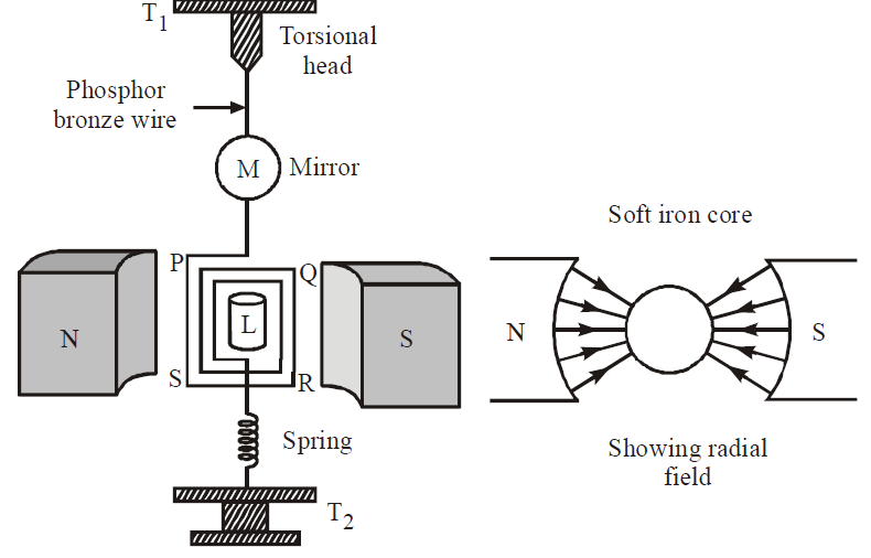
It essentially consists of a rectangular coil PQRS or a cylindrical coil of large number of turns of fine insulated wire wound over a non-conducting frame of ivory or bamboo. This coil is suspended by means of phosphor bronze wire between the pole pieces of a powerful horseshoe magnet NS. The poles of the magnet are curved to make the field radial. The lower end of the coil, is attached to a spring of phosphor-bronze wire. The spring and the free ends of phosphor bronze wire are joined to two terminals T2 and T1 respectively on the top of the case of the instrument. L is a soft iron core. A small mirror M is attached on the suspension wire. Using lamp and scale arrangement, the deflection of the coil can be recorded. The whole arrangement is enclosed in a non-metallic case.
THEORY
Let the coil be suspended freely in the magnetic field.
Suppose, n = number of turns in the coil
A = area of the coil
B = magnetic field induction of radial magnetic field in which the coil is suspended.
Here, the magnetic field is radial, i.e., the plane of the coil always remains parallel to the direction of magnetic field, and hence the torque acting on the coil
τ = niAB … (1)
Due to this torque, the coil rotates. As a result, the suspension wire gets twisted. Now a restoring torque is developed in the suspension wire. The coil will rotate till the deflecting torque acting on the coil due to flow of current through it is balanced by the restoring torque developed in the suspension wire due to twisting. Let C be the restoring couple for unit twist in the suspension wire and θ be the angle through which the coil has turned. The couple for this twist θ is Cθ.
In equilibrium, deflecting couple = restoring couple
∴ ni AB = Cθ or i = Cθ/ (nAB)
or i = Kθ (where C/nAB = K) … (2)
K is a constant for galvanometer and is known as galvanometer constant.
Hence 
Therefore, the deflection produced in the galvanometer is directly proportional to the current flowing through it.
Current sensitivity of the galvanometer : The current sensitivity of a galvanometer is defined as the deflection produced in the galvanometer when a unit current is passed through it.
We know that, niAB = Cθ
∴ Current sensitivity, is = 
where C = restoring couple per unit twist
The SI unit of current sensitivity is radian per ampere or deflection per ampere.
Voltage sensitivity of the galvanometer : The voltage sensitivity of the galvanometer is defined as the deflection produced in the galvanometer when a unit voltage is applied across the terminals of the galvanometer.
∴ Voltage sensitivity ,
,
If R be the resistance of the galvanometer and a current is passed through it, then V = iR
∴ Voltage sensitivity, Vs = 
The SI. unit of voltage sensitivity is radian per ampere or deflection per ampere.
Conditions for sensitivity : A galvanometer is said to be more sensitive if it shows a large deflection even for a small value of current.
We know that,
For a given value of i, θ will be large if (i) n is large, (ii) A is large, (iii) B is large, and (iv) C is small.
Regarding above factors, n and A cannot be increased beyond a certain limit. By increasing n, the resistance of the galvanometer will increase and by increasing A, the size of the galvanometer will increase. So, the sensitivity will decrease. Therefore, B is increased. The value of B can be increased by using strong horseshoe magnet. Further, the value of C can be decreased. The value of C for quartz and phosphor-bronze is very small. So, the suspension wire of quartz or phosphor-bronze is used. The value of C is further decreased if the wire is hammered into a flat strip.
HALL EFFECT
When a current passes through a slab of material in the presence of a transverse magnetic field, a small potential difference is established in a direction perpendicular to both, the current flow and the magnetic field. This effect is called Hall effect.
The voltage thus developed is called Hall voltage.
Hall effect enables us to :
- Determine the sign of charge carriers inside the conductor.
- Calculate the number of charge carriers per unit volume.
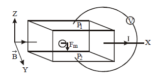
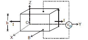
EXPLANATION
Let us consider a conductor carrying current in +X direction. The magnetic field is applied along +Y direction. Consider two points P1 and P2 on the conductor and connect a voltmeter between these points. If no magnetic field is applied across the conductor, then the points P1 and P2 will be at same potential and there will be no deflection in the galvanometer. However, if a magnetic field is applied as shown in the figure, then the Lorentz force acts on electrons as shown in the figure.
The Lorentz force on electrons Fm = –e  acts in the downwards direction.
Now there may be two cases:
Case I : If the charge particles are negatively charged, then these negative charges will accumulate at the point P2 and therefore P2 will be at lower potential than P1.
Case II : If the charged particles are positively charged, then the point P2 will be at higher potential than P1.
Magnitude of hall voltage :
Let w be width and A be the cross-sectional area of the conductor. If e is magnitude of charge or the current carrier (electron or hole).
The force on the current carrier due to magnetic field B,
Fm = Bevd
Here, vd is drift velocity of the current carries.
Due to the force Fm, the opposite charges build up at the points P1 and P2 of the conductor.
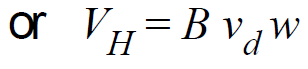
If VH is Hall voltage developed across the two faces, then the strength of electric field due to Hall voltage is given by
EH =  .
.
Here w = P1P2.
This electric field exerts an electric force on the current carries in a direction opposite to that of magnetic force.
The magnitude of this force is 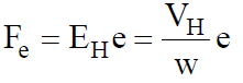
In equilibrium condition, Fe = Fm,
or 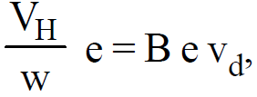
Now, drift velocity of current carrier is given by, vd = 
where n is the number of current carries per unit volume of the strip.
Hall resistance ,
,
∴ Hall voltage 
KEEP IN MEMORY
Hall effect can determine nature of current (charge) carriers in the material. i.e. whether the charge is +ve or –ve.
Hall voltage 
where n is the density of charge carriers
b = thickness of plate,
B = magnetic field,
I = current flowing through plate,
A = area of cross-section of plates