Chapter-4: Moving Charges and Magnetism of NCERT class 12 Physics note is available here.
Moving Charges and Magnetism is one of the important chapters of CBSE class 12 Physics. So, students must prepare this chapter thoroughly. The notes provided here will be very helpful for the students who are going to appear in CBSE class 12 Physics board exam .
Oersted’ Experiment
During a lecture demonstration in 1820, the Danish physicist Hans Christian Oersted noticed that a current in a straight wire caused a noticeable deflection in a nearby magnetic compass needle. He further investigated this phenomenon and confirmed the phenomenon of magnetic field around current carrying conductor.
Magnetic Field
It is the space around a magnet or current carrying conductor around which magnetic effects can be experienced. It is a vector quantity and its SI unit is tesla (T) or Wbm‒2.
Moving Charge & Magnetic Field
A charge can produce magnetic field if it is in motion. Magnetic field can also interact with a moving charge.
Lorentz Force
Assume a point charge q (moving with a velocity v and, located at r at a given time t) in presence of both the electric field E (r) and the magnetic field B (r). The force on an electric charge q due to both of them is given by,
F = q [E (r) + v × B (r)] ≡ FElectric + FMagnetic
Careful analysis of this expression shows that:
• Lorentz Force depends on q, v and B (charge of the particle, the velocity and the magnetic field). Force on a negative charge is opposite to that on a positive charge.
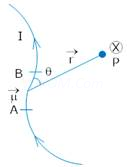
• The magnetic force q [v × B] includes a vector product of velocity & magnetic field. Vector product makes the force due to magnetic field become zero if velocity and magnetic field are parallel or anti-parallel. The force acts in a (sideways) direction perpendicular to both the velocity and the magnetic field. Its direction is given by the screw rule or right hand rule for vector (or cross) product as shown in figure given below
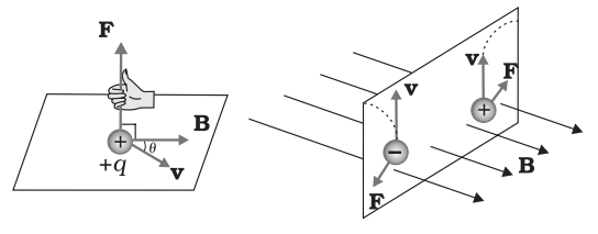
Image Source: NCERT Books
• The magnetic force is zero if charge is not moving (as then |v|= 0). Only a moving charge feels the magnetic force
F = q [v × B] =q |v||B| sin θ ň, where θ is angle between v and B.
Magnetic force on a current-carrying conductor
Magnetic force on a conductor of length l carrying a current I placed in a uniform magnetic field B is given by
F = I (l × B) or |F| = I |l|| B| sin θ.
The direction of F is perpendicular to both l and B and can be obtained with the help of Fleming’s Left hand rule.
Motion of a charged particle in Magnetic Field
A force on a particle does work if the force has a component along (or opposed to) the direction of motion of the particle.
In the case of motion of a charge in a magnetic field, the magnetic force is perpendicular to the velocity of the particle. So no work is done and no change in the magnitude of the velocity is produced (though the direction of momentum may be changed).
Generally two types of cases are possible:
Case 1st: When v is perpendicular to B
The perpendicular force, q v × B, acts as a centripetal force and produces a circular motion perpendicular to the magnetic field. The particle will describe a circle if v and B are perpendicular to each other.
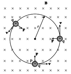
Image Source: NCERT Books
In this case, radius described by charge particle is given by, r = m v / q B
If ω is the angular frequency, then ω = 2πv = q B / m, where, v is frequency of rotation
The time taken for one revolution is T= 2π/ω ≡ 1/ν.
Case 2nd: When v is making an angle with B other than 0o
In this case, velocity has a component along B, this component remains unchanged as the motion along the magnetic field will not be affected by the magnetic field. The motion in a plane perpendicular to B is as before a circular one, thereby producing a helical motion
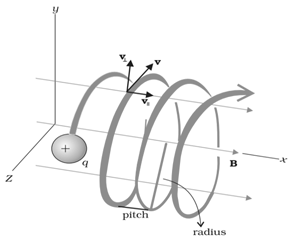
Image Source: NCERT Books
The distance moved along the magnetic field in one rotation is called pitch p and,
p = v||T = 2πm v|| / q B
The radius of the circular component of motion is called the radius of the helix.
Motion of a charge in Combined Electric and Magnetic Fields
A charge q moving with velocity v in presence of both electric and magnetic fields experiences a force given by F = q (E + v × B) = FE + FB
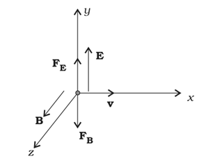
Image Source: NCERT Books
Consider the situation shown in figure given above, in this particular case we have:
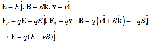
Here, electric and magnetic forces are in opposite directions as shown in the figure.
If we adjust the value of E and B such that magnitude of the two forces are equal. Then, total force on the charge is zero and the charge will move in the fields undeflected.
This happens when, qE = qvB or v = E/B
This condition can be used to select charged particles of a particular velocity out of a beam containing charges moving with different speeds (irrespective of their charge and mass). The crossed E and B fields, therefore, serve as a velocity selector.
Only particles with speed E/B pass undeflected through the region of crossed fields.
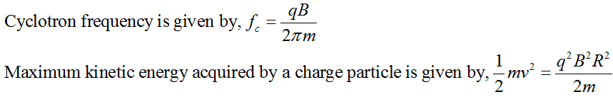
Cyclotron:
It is a machine to accelerate charged particles or ions to high energies.
The cyclotron uses both electric and magnetic fields in combination to increase the energy of charged particles. As the fields are perpendicular to each other they are called crossed fields.
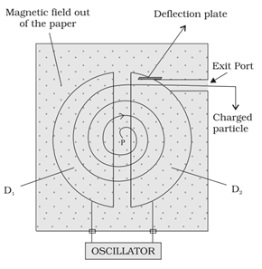
Image Source: NCERT Books
A schematic sketch of the cyclotron is shown in the figure given above. There is a source of charged particles or ions at P which move in a circular fashion in the dees, D1 and D2, on account of a uniform perpendicular magnetic field B. An alternating voltage source accelerates these ions to high speeds. The ions are eventually ‘extracted’ at the exit port.
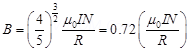
In case of cyclotron,
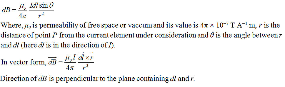
Magnetic Field Due to a Current Element: Biot-Savart Law
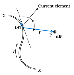
Image Source: NCERT Textbooks
Magnetic field strength at a point P due to a small length dl of the conductor carrying current I is given by,
CBSE Class 12th Chemistry Notes: Polymers
Magnetic Field on the Axis of a Circular Current Loop:
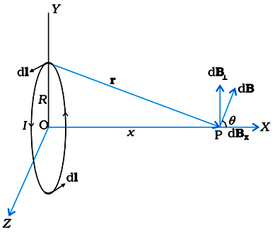
Image Source: NCERT Textbooks
Magnetic field at a point on the axis of a coil, having radius R, distance x from the centre of the coil is given by,
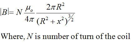
Magnetic field at the centre of a current carrying coil:
To find the magnetic field at the centre of the coil, we can put x = 0 is above equation.
So, B at the centre of a current carrying coil on N turn is given by,
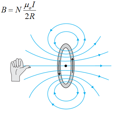
Image Source: NCERT Textbooks
The magnetic field lines due to a circular wire form closed loops and are shown in the figure given above. The direction of the magnetic field is given by right-hand thumb rule which is if we curl the palm of our right hand around the circular wire with the fingers pointing in the direction of the current then; the right-hand thumb gives the direction of the magnetic field.
CBSE Class 12th Physics Notes: Electrostatics Potential and Capacitance
Ampere’s Circuital Law
According to this law, the line integral of magnetic field B around any closed path in vacuum is μo times the net current (I) threading through the area enclosed by the curve.
![]()
Magnetic field due to a solenoid
Solenoid is a device used to generate magnetic fields. It consists of a long conducting wire wound in the form of a helix where the neighboring turns are closely spaced. When current flows in the solenoid, then each turn can be regarded as conducting circular loop. The net magnetic field is the vector sum of the fields due to all the turns. Enameled wires are used for winding so that turns are insulated from each other.
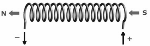
Image Source: wikipedia.org
With the help of Ampere’s circuital law we can calculate the magnetic field due to a solenoid.
Magnetic field at the centre of a long solenoid having n turns per unit length and carrying a current I is given by: B = μo n I
The direction of the field is given by the right-hand rule. The solenoid is commonly used to obtain a uniform magnetic field.
CBSE Class 12th Chemistry Notes: Haloalkanes and Haloarenes (Part – II)
Magnetic field due to a toroid
Toroid is a hollow circular ring on which a large number of turns of a wire are closely wound. It can be viewed as a solenoid which has been bent into a circular shape to close on itself.
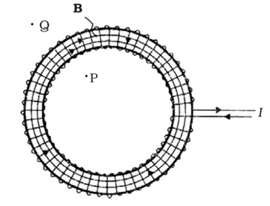
Image Source: NCERT Textbooks
The magnetic field in the open space inside (point P) and exterior to the toroid (point Q) is zero. The field B inside the toroid is constant in magnitude for the ideal toroid of closely wound turns and is given by, B = μo n I.
Force between two Parallel Current Carrying Wires
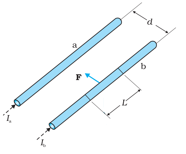
Image Source: NCERT textbooks
Two long parallel conductors a and b kept at a distance d apart in vaccum and carrying a current Ia and Ib respectively. The force per unit length experienced by each of them is given by
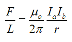
This force will be equal and opposite on both wires.
Nature of force of interaction between the current carrying conductors can be explained on the basis of Fleming’s left hand rule.
In general, two long parallel conductors carrying current
- in same direction will attract each other
- in different direction will repel each other
Definition of Ampere
Definition of ampere follows from the formula for force between two parallel current carrying conductors.
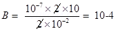
When 1 ampere each is passing through two long, parallel conductors kept 1 m apart in vacuum, a force of magnitude 2 × 10‒7 N is experienced by a meter length of each conductor.
Torque on a Rectangular Current loop in a Uniform Magnetic Field
A rectangular loop having N turns of area A each, carrying a steady current I and placed in a uniform magnetic field B such that the normal to the plane of the loop makes an angle θ with the direction of the magnetic field B, then a torque τ experienced by the loop whose magnitude is given by, τ = NIAB sinθ.
This equation can be expressed in vector form as shown below:
![]()
Here, |m| = NIA is called magnetic dipole moment of the current loop.
One can define magnetic dipole moment of the current carrying loop as product of current in the loop and total area of the loop, i.e., M = I (NA).
Magnetic dipole moment is a vector quantity and its direction is along the direction of magnetic field due to the current in the loop. We can also find the direction of dipole moment vector with the help of right hand grip rule.
Magnetic Dipole Moment of a Revolving Electron
Any charge in uniform circular motion would have an associated magnetic moment given by,
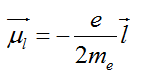
Here, e = 1.6 × 10‒19 C, me = 9.1 × 10‒31 kg, l is the magnitude of the angular momentum of the electron about the central nucleus (“orbital” angular momentum) and |l| = (n h)/2π, where, n is a natural number (n = 1, 2, 3, ….) and h is a constant named after Max Planck (Planck’s constant) with a value h = 6.626 × 10⁻³⁴ J s.
The negative sign indicates that the angular momentum of the electron is opposite in direction to the magnetic moment. Instead of electron with charge (– e), if we had taken a particle with charge (+ q), the angular momentum and magnetic moment would be in the same direction.
Potential Energy of a current loop in a Magnetic Field
If a current loop of magnetic moment, M = NIA is held in a uniform magnetic field B in such a way that direction of magnetic dipole moment makes an angle θ with the direction of magnetic field, then the potential energy of the dipole is given by,
![]()
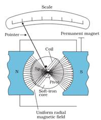
Moving Coil Galvanometer
It is an instrument used for detection and measurement of small current.
The galvanometer consists of a light rectangular coil of N turns each having area A wound on an aluminium frame.
The coil is free to rotate free to rotate about a fixed axis (as shown in figure given below), in a uniform radial magnetic field.
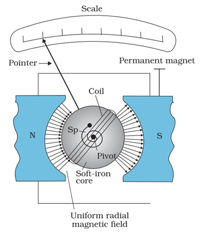
Image Source: NCERT textbooks
There is a cylindrical soft iron core which is used to make the field radial and also to increase the strength of the magnetic field.
When a current flows through the coil, a torque acts on it. This torque is given by, τ = NIAB where the symbols have their usual meaning.
Since the field is radial by design, we have taken sin θ = 1 in the above expression for the torque. The magnetic torque NIAB tends to rotate the coil. A spring Sp provides a counter torque kϕ that balances the magnetic torque NIAB; resulting in a steady angular deflection ϕ. In equilibrium
kϕ = NI AB
Here, k is the torsional constant of the spring; i.e. the restoring torque per unit twist.
The deflection ϕ is indicated on the scale by a pointer attached to the spring. We have
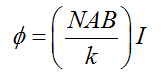
The quantity in brackets is a constant for a given galvanometer.
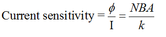
Sensitivity of a Galvanometer
Current Sensitivity:
Current sensitivity of a galvanometer is defined as the deflection per unit current
Mathematically,
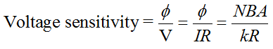
Voltage Sensitivity:
Voltage sensitivity of a galvanometer is defined as the deflection per as the deflection per unit voltage.
Mathematically,
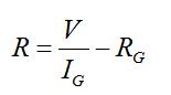
Conversion of a Galvanometer into Voltmeter
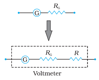
Image Source: NCERT textbooks
A galvanometer of coil resistance RG, showing full scale deflection for a current IG can be converted into a voltmeter for measuring potential differences having values greater than IGRG by connecting high resistance R in series with the galvanometer where,
An ideal voltmeter has infinite resistance.
Conversion of a Galvanometer into Ammeter:
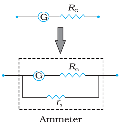
Image Source: NCERT textbooks
A galvanometer of coil resistance RG, showing full scale deflection for a current IG can be converted into an ammeter for measuring current having values more than IG (i.e., I > IG) by putting a low resistance rS in parallel with the galvanometer where,
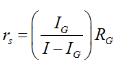
Here, rs is also called shunt resistance. An ideal ammeter has zero resistance.
CBSE Class 12 Physics Important Questions Chapter 4 – Moving Charges and Magnetism
1 Mark Questions
1. State two properties of the material of the wire used for suspension of the coil in a moving coil galvanometer?
Ans. (a) Non-Brittle conductor
(b) Restoring Torque per unit Twist should be small.
2. What will be the path of a charged particle moving along the direction of a uniform magnetic field?
Ans. The path of a charged particle will be a straight line path as no force acts on the particle.
3. Two wires of equal lengths are bent in the form of two loops. One of the loop is square shaped whereas the other loop is circular. These are suspended in a uniform magnetic field and the same current is passed through them. Which loop will experience greater torque? Give reasons?
Ans. since 
Since Area of – circular loops is more Than of a square loop Torque experienced by a circular loop is greater.
4. A cyclotron is not suitable to accelerate electron. Why?
Ans. A cyclotron is not suitable to accelerate electron because its mass is less due to which they gain speed and step out of the dee immediately.
2 Marks Questions
1. A steady current flows in the network shown in the figure. What will be the magnetic field at the centre of the network?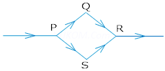
Ans. Zero, because magnetic field at the centre of the loop is just equal and opposite i.e. magnetic field due 1- PQR is equal and opposite to that of PSR.
2. An ∝– particle and a proton are moving in the plane of paper in a region where there is uniform magnetic field B directed normal to the plane of paper. If two particles have equal linear momenta, what will be the ratio of the radii of their trajectories in the field?
Ans. Since radius of the path (R) = 
=> R
=> 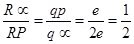
=> R∝: Rp = 1:2.
3. Give one difference each between diamagnetic and ferromagnetic substances. Give one example of each?
Ans. Diamagnetic substances are weakly repelled by a magnet eg. Gold.
Ferromagnetic materials are strongly attracted by a magnet eg. Iron.
4. Write the expression for the force acting on a charged particle of charge q moving with velocity is in the presence of magnetic field B. Show that in the presence of this force.
(a) The K.E. of the particle does not change.
(b) Its instantaneous power is zero.
Ans. Since F = q (
 )
)
(a) Since direction of force is perpendicular to the plane containing  )
)
=> w = Fs cos

w = Fs  = 0
= 0
=> KE = 0 KE will not – change
(b) since p = Fvcos = Fv = 0
=> Instantaneous power is also zero.
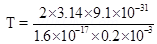
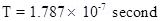
5. An electron of kinetic energy 25KeV moves perpendicular to the direction of a uniform magnetic field of 0.2 millitesla calculate the time period of rotation of the electron in the magnetic field?
Ans. B = 0.2 T = 0.2 10-3T
10-3T
Time Period T = 
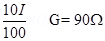
6. It is desired to pass only 10% of the current through a galvanometer of resistance 90  . How much shunt resistance be connected across the galvanometer?
Ans. IG = 10% of I = 
S = 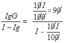
S = 
S = 
=> 
3 Marks Questions
1. Derive an expression for the force acting on a current carrying conductor placed in a uniform magnetic field Name the rule which gives the direction of the force. Write the condition for which this force will have (1) maximum (2) minimum value?
Ans. A conductor is placed in a uniform magnetic field  which makes and angle
  with . Let I current flows through the conductor.
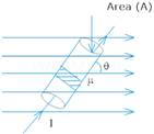
If n is the no. of electrons per unit volume of the conductor, then Total no. of electrons in small current element d = nAdl
=>= Ne
=> = nAdl e be the force experienced by each electron = e

Force experienced by small current element

dF = neAvd dl B sin
(I = neAvd)
=> df = IdlBsin
Hence total force experienced
F = 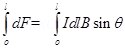
F = IB
In vector form  = I
= I 
(a) Force will be maximum when = 900
(b) Force will be minimum when = 00
2. A straight wire carries a current of 10A. An electron moving at  is at distance 2.0 cm from the wire. Find the force acting on the electron if its velocity is directed towards the wire?
Ans. Here I = 10A
R = 2.0 cm = 2
Force acting on moving electron (F) = qVB sin
 tesla and
  to the plane of paper and directed downwards.
Now 
 Newton.
3. State Biot- Savarts law. Derive an expression for magnetic field at the centre of a circular coil of n-turns carrying current – I?
Ans. Biot – Savart law states that the magnetic field db due to a current element  at any point is
ie dB  I
I
dB dl
dB sin
dB 
Combining all we get
dB 

Consider a circular loop of radius r carrying a current I.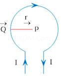
Since dl 
=> 
Applying Biot Savart law
dB = 
For entire closed circular loop
B = 
B = 
For n turns of a coil 
4. What is radial magnetic field? How it is obtained in moving coil galvanometer?
Ans. A radial magnetic field is one in which plane of the coil always lies in the direction of the magnetic field. It can be obtained by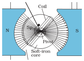
(a) Properly cutting the pole pieces concave in shape.
(b) Placing soft iron cylindrical core between the pole pieces.
5. Two straight parallel current carrying conductors are kept at a distanced r from each other in air. The direction for current in both the conductor is same. Find the magnitude and direction of the force between them. Hence define one ampere?
Ans. Consider two parallel conductors carrying or current  and is separated by a distance ‘d’.
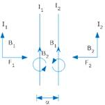
Magnetic field due to current  at any paint on conductor (2) is
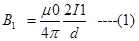
(to the plane & Downwards  )
)
Since current carrying conductor is placed at right angles to the magnetic field
=> F = BI l 
F = B I l
=> Force experienced per unit length of conductor —-(2)
 =
=  —-(2)
—-(2)
Fleming’s left hand Rule says is directed towards conductor (1)
Similarly  (Directed Towards conductor (2))
Since  are equal and opposite so two parallel current carrying conductor attract each other.
Since F = 
If = 1A d = 1m
Thus one ampere is that current which is flowing in two infinitely long parallel conductors separated by a distance of 1 meter in vacuum and experiences a force of on each meter of the other wire.
6. A circular coil of wire consisting of 100 turns, each of radius 8.0 cm carries a current of 0.40 A. What is the magnitude of the magnetic field B at the centre of the coil?
Ans. Number of turns on the circular coil, n = 100
Radius of each turn, r = 8.0 cm = 0.08 m
Current flowing in the coil, I = 0.4 A
Magnitude of the magnetic field at the centre of the coil is given by the relation,
| B | = 
Where,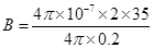

 = Permeability of free space
= 4π × 10–7 T m A–1
| B |=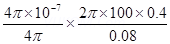

Hence, the magnitude of the magnetic field is .
7. A long straight wire carries a current of 35 A. What is the magnitude of the field B at a point 20 cm from the wire?
Ans. Current in the wire, I = 35 A
Distance of a point from the wire, r = 20 cm = 0.2 m
Magnitude of the magnetic field at this point is given as:
B 

Where, = Permeability of free space = 
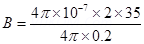

Hence, the magnitude of the magnetic field at a point 20 cm from the wire is
8. A long straight wire in the horizontal plane carries a current of 50 A in north to south direction. Give the magnitude and direction of B at a point 2.5 m east of the wire.
Ans. Current in the wire, I = 50 A
A point is 2.5 m away from the East of the wire. Magnitude of the distance of the point from the wire, r = 2.5 m.
Magnitude of the magnetic field at that point is given by the relation, B
Where,= Permeability of free space = 
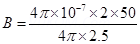

The point is located normal to the wire length at a distance of 2.5 m. The direction of the current in the wire is vertically downward. Hence, according to the Maxwell’s right hand thumb rule, the direction of the magnetic field at the given point is vertically upward.
9. A horizontal overhead power line carries a current of 90 A in east to west direction. What is the magnitude and direction of the magnetic field due to the current 1.5 m below the line?
Ans. Current in the power line, I = 90 A
Point is located below the power line at distance, r = 1.5 m
Hence, magnetic field at that point is given by the relation,
B
Where,= Permeability of free space = 

The current is flowing from East to West. The point is below the power line. Hence, according to Maxwell’s right hand thumb rule, the direction of the magnetic field is towards the South.
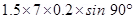
10. What is the magnitude of magnetic force per unit length on a wire carrying a current of 8 A and making an angle of 30º with the direction of a uniform magnetic field of 0.15 T?
Ans. Current in the wire, I = 8 A
Magnitude of the uniform magnetic field, B = 0.15 T
Angle between the wire and magnetic field,  = 30°.
Magnetic force per unit length on the wire is given as:
f= BI sin
= 
=
Hence, the magnetic force per unit length on the wire is.
11. A 3.0 cm wire carrying a current of 10 A is placed inside a solenoid perpendicular to its axis. The magnetic field inside the solenoid is given to be 0.27 T. What is the magnetic force on the wire?
Ans. Length of the wire, l = 3 cm = 0.03 m
Current flowing in the wire, I = 10 A
Magnetic field, B = 0.27 T
Angle between the current and magnetic field, = 90°
Magnetic force exerted on the wire is given as:
F= BIl sin
= 
= 
Hence, the magnetic force on the wire is . The direction of the force can be obtained from Fleming’s left hand rule.
12. Two long and parallel straight wires A and B carrying currents of 8.0 A and 5.0 A in the same direction are separated by a distance of 4.0 cm. Estimate the force on a 10 cm section of wire A.
Ans. Current flowing in wire A, 
Current flowing in wire B, 
Distance between the two wires, r = 4.0 cm = 0.04 m
Length of a section of wire A, l = 10 cm = 0.1 m
Force exerted on length l due to the magnetic field is given as:
Where, = Permeability of free space =

The magnitude of force is . This is an attractive force normal to A towards B because the direction of the currents in the wires is the same.
13. A closely wound solenoid 80 cm long has 5 layers of windings of 400 turns each. The diameter of the solenoid is 1.8 cm. If the current carried is 8.0 A, estimate the magnitude of B inside the solenoid near its centre.
Ans. Length of the solenoid, l = 80 cm = 0.8 m
There are five layers of windings of 400 turns each on the solenoid.
Total number of turns on the solenoid, N = 5 × 400 = 2000
Diameter of the solenoid, D = 1.8 cm = 0.018 m
Current carried by the solenoid, I = 8.0 A
Magnitude of the magnetic field inside the solenoid near its centre is given by the relation,
Where, = Permeability of free space =


Hence, the magnitude of the magnetic field inside the solenoid near its centre is
14. A square coil of side 10 cm consists of 20 turns and carries a current of 12 A. The coil is suspended vertically and the normal to the plane of the coil makes an angle of  with the direction of a uniform horizontal magnetic field of magnitude 0.80 T. What is the magnitude of torque experienced by the coil?
Ans. Length of a side of the square coil, l = 10 cm = 0.1 m
Current flowing in the coil, I = 12 A
Number of turns on the coil, n = 20
Angle made by the plane of the coil with magnetic field, 
Strength of magnetic field, B = 0.80 T
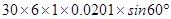
Magnitude of the magnetic torque experienced by the coil in the magnetic field is given by the relation,
T = n BIA sinθ
Where,
A = Area of the square coil

= 0.96 N m
Hence, the magnitude of the torque experienced by the coil is 0.96 N m.
15. (a) A circular coil of 30 turns and radius 8.0 cm carrying a current of 6.0 A is suspended vertically in a uniform horizontal magnetic field of magnitude 1.0 T. The field lines make an angle of  with the normal of the coil. Calculate the magnitude of the counter torque that must be applied to prevent the coil from turning.
(b) Would your answer change, if the circular coil in (a) were replaced by a planar coil of some irregular shape that encloses the same area? (All other particulars are also unaltered.)
Ans. (a) Number of turns on the circular coil, n = 30
Radius of the coil, r = 8.0 cm = 0.08 m
Area of the coil 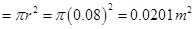
Current flowing in the coil, I = 6.0 A
Magnetic field strength, B = 1 T
Angle between the field lines and normal with the coil surface,
The coil experiences a torque in the magnetic field. Hence, it turns. The counter torque applied to prevent the coil from turning is given by the relation, … (i)
… (i)
= 
= 3.133 N m
(b) It can be inferred from relation (i) that the magnitude of the applied torque is not dependent on the shape of the coil. It depends on the area of the coil. Hence, the answer would not change if the circular coil in the above case is replaced by a planar coil of some irregular shape that encloses the same area.
16. A magnetic field of 100 G  is required which is uniform in a region of linear dimension about 10 cm and area of cross-section about
  . The maximum current-carrying capacity of a given coil of wire is 15 A and the number of turns per unit length that can be wound round a core is at most 1000 turns
  . Suggest some appropriate design particulars of a solenoid for the required purpose. Assume the core is not ferromagnetic.
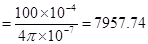
Ans. Magnetic field strength, B = 100 
Number of turns per unit length, 
Current flowing in the coil, I = 15 A
Permeability of free space, =
Magnetic field is given by the relation, 


If the length of the coil is taken as 50 cm, radius 4 cm, number of turns 400, and current 10 A, then these values are not unique for the given purpose. There is always a possibility of some adjustments with limits.
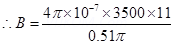
17. A toroid has a core (non-ferromagnetic) of inner radius 25 cm and outer radius 26 cm, around which 3500 turns of a wire are wound. If the current in the wire is 11 A, what is the magnetic field (a) outside the toroid, (b) inside the core of the toroid, and (c) in the empty space surrounded by the toroid.
Ans. Inner radius of the toroid,  = 0.25 m
Outer radius of the toroid,  = 0.26 m
Number of turns on the coil, N = 3500
Current in the coil, I = 11 A
(a) Magnetic field outside a toroid is zero. It is non-zero only inside the core of a toroid.
(b) Magnetic field inside the core of a toroid is given by the relation,
Where, = Permeability of free space =
l = length of toroid


(c) Magnetic field in the empty space surrounded by the toroid is zero.
18. Answer the following questions:
(a) A magnetic field that varies in magnitude from point to point but has a constant direction (east to west) is set up in a chamber. A charged particle enters the chamber and travels undeflected along a straight path with constant speed. What can you say about the initial velocity of the particle?
(b) A charged particle enters an environment of a strong and non-uniform magnetic field varying from point to point both in magnitude and direction, and comes out of it following a complicated trajectory. Would its final speed equal the initial speed if it suffered no collisions with the environment?
(c) An electron travelling west to east enters a chamber having a uniform electrostatic field in north to south direction. Specify the direction in which a uniform magnetic field should be set up to prevent the electron from deflecting from its straight line path.
Ans.(a) The initial velocity of the particle is either parallel or anti-parallel to the magnetic field. Hence, it travels along a straight path without suffering any deflection in the field.
(b) Yes, the final speed of the charged particle will be equal to its initial speed. This is because magnetic force can change the direction of velocity, but not its magnitude.
(c) An electron travelling from West to East enters a chamber having a uniform electrostatic field in the North-South direction. This moving electron can remain undeflected if the electric force acting on it is equal and opposite of magnetic field. Magnetic force is directed towards the South. According to Fleming’s left hand rule, magnetic field should be applied in a vertically downward direction.
19. A straight horizontal conducting rod of length 0.45 m and mass 60 g is suspended by two vertical wires at its ends. A current of 5.0 A is set up in the rod through the wires.
(a) What magnetic field should be set up normal to the conductor in order that the tension in the wires is zero?
(b) What will be the total tension in the wires if the direction of current is reversed keeping the magnetic field same as before? (Ignore the mass of the wires.)  .
.
Ans. Length of the rod, l = 0.45 m
Mass suspended by the wires, m = 60 g =
Acceleration due to gravity,
Current in the rod flowing through the wire, I = 5 A
(a) Magnetic field (B) is equal and opposite to the weight of the wire i.e., BIl + mg
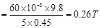
A horizontal magnetic field of 0.26 T normal to the length of the conductor should be set up in order to get zero tension in the wire. The magnetic field should be such that Fleming’s left hand rule gives an upward magnetic force.
(b) If the direction of the current is revered, then the force due to magnetic field and the weight of the wire acts in a vertically downward direction.
∴Total tension in the wire = BIl + mg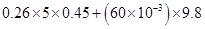
= 1.176 N
20. The wires which connect the battery of an automobile to its starting motor carry a current of 300 A (for a short time). What is the force per unit length between the wires if they are 70 cm long and 1.5 cm apart? Is the force attractive or repulsive?
Ans. Current in both wires, I = 300 A
Distance between the wires, r = 1.5 cm = 0.015 m
Length of the two wires, l = 70 cm = 0.7 m
Force between the two wires is given by the relation,
Where, = Permeability of free space = 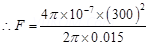
=1.2 N/m
Since the direction of the current in the wires is opposite, a repulsive force exists between them.
21. A circular coil of 20 turns and radius 10 cm is placed in a uniform magnetic field of 0.10 T normal to the plane of the coil. If the current in the coil is 5.0 A, what is the
(a) total torque on the coil,
(b) total force on the coil,
(c) average force on each electron in the coil due to the magnetic field?
(The coil is made of copper wire of cross-sectional area  , and the free electron density in copper is given to be about
  .)
.)
Ans. Number of turns on the circular coil, n = 20
Radius of the coil, r = 10 cm = 0.1 m
Magnetic field strength, B = 0.10 T
Current in the coil, I = 5.0 A
(a) The total torque on the coil is zero because the field is uniform.
(b) The total force on the coil is zero because the field is uniform.
(c) Cross-sectional area of copper coil, A =
Number of free electrons per cubic meter in copper, N =
Charge on the electron, 
Magnetic force, 
Where, = Drift velocity of electrons


Hence, the average force on each electron is
22. galvanometer coil has a resistance of 12  and the metre shows full scale deflection for a current of 3 mA. How will you convert the metre into a voltmeter of range 0 to 18 V?
Ans. Resistance of the galvanometer coil, G = 12
Current for which there is full scale deflection,  = 3 mA =
Range of the voltmeter is 0, which needs to be converted to 18 V.
Let a resistor of resistance R be connected in series with the galvanometer to convert it into a voltmeter. This resistance is given as:
= 
Hence, a resistor of resistance is to be connected in series with the galvanometer.
23. A galvanometer coil has a resistance of 15 and the metre shows full scale deflection for a current of 4 mA. How will you convert the metre into an ammeter of range 0 to 6 A?
Ans. Resistance of the galvanometer coil, G = 15
Current for which the galvanometer shows full scale deflection, = 4 mA = 
Range of the ammeter is 0, which needs to be converted to 6 A.Current, I = 6 A
A shunt resistor of resistance S is to be connected in parallel with the galvanometer to convert it into an ammeter. The value of S is given as:


Hence, a  shunt resistor is to be connected in parallel with the galvanometer.
5 Marks Questions
1. (a) What is cyclotron? Explain its working principle?
(b) A cyclotron’s oscillator frequency is 10MHz what should be the operating magnetic field for accelerating protons? If radius of its dees is 20cm, what is the K.E. of the proton beam produced by the accelerator? (  ,
,  ,
,  )?
)?
Ans. (a) It is a device used to accelerate charged particles like protons, deuterons,  – particle etc.
It is based on the principle that a charged particle can be accelerated to very high energies by making it pass through a moderate electric field a number of times and applying a strong magnetic field at the same time.
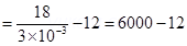
(b) v = 10MHz = 10 106 Hz
r = 20cm = 
KE = 


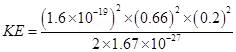
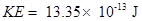
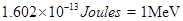
Since 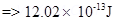

2. (a) Draw a labelled diagram of a moving coil galvanometer. Prove that in a radial magnetic field, the deflection of the coil is directly proportional to the current flowing in the coil.
(b) A galvanometer can be converted into a voltmeter to measure upto
(i) V volt by connecting a resistance  series with the coil
(ii)  volt by connecting a resistance
  in series with coil Find R in terms of
  required to convert – it into a voltmeter that can read upto ‘2v’ volt.
Ans. (a) When a current I is passed through a coil two equal and opposite forces acts on the arms of a coil to form a couple which exerts a Torque on the coil.
=> 
If  =
= 
 is the angle made by the normal to the plane of coil with B
 = NIAB —-(1)
This is called as deflecting torque
As the coil deflected the spring is twisted and a restoring torque per unit twist then the restoring torque for the deflecting & is given by = k
= k  —-(2)
—-(2)
In equilibrium
Deflecting Torgue=Restoring Torgue
NIAB = K
I = 
I = G where G =  (galvanometer constant)
=> 
Thus deflection of the coil is directly proportional to the current flowing in the coil.
(b) We know Ig = 
=> Ig =  —–(1)
—–(1)
And Ig = 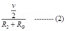
Equating (1) & (2)
For conversion Ig = 
=> Ig 


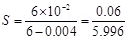
3. Two moving coil meters, M1 and M2 have the following particulars: ,
, 
 ,
, 
 ,
, 
 ,
, 
(The spring constants are identical for the two meters).
Determine the ratio of (a) current sensitivity and (b) voltage sensitivity of 
Ans. For moving coil meter M1:
Resistance,
Number of turns,
Area of cross-section, 
Magnetic field strength,
Spring constant 
For moving coil meter M2:
Resistance,
Number of turns,
Area of cross-section, 
Magnetic field strength,
Spring constant, 
(a) Current sensitivity of is given as:
And, current sensitivity of is given as:
 Ratio
Ratio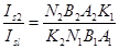
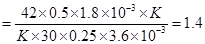
Hence, the ratio of current sensitivity of  is 1.4.
(b) Voltage sensitivity for is given as:
And, voltage sensitivity for is given as:
4. In a chamber, a uniform magnetic field of 6.5 G  is maintained. An electron is shot into the field with a speed of
  normal to the field. Explain why the path of the electron is a circle. Determine the radius of the circular orbit. (e =
  , me=
, me=  )
)
Ans.Magnetic field strength, B = 6.5 G = 
Speed of the electron, v = 
Charge on the electron, e =
Mass of the electron, 
Angle between the shot electron and magnetic field, 
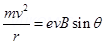
Magnetic force exerted on the electron in the magnetic field is given as:
F = evB 
This force provides centripetal force to the moving electron. Hence, the electron starts moving in a circular path of radius r.
Hence, centripetal force exerted on the electron,
In equilibrium, the centripetal force exerted on the electron is equal to the magnetic force i.e.,


= 4.2 cm
Hence, the radius of the circular orbit of the electron is 4.2 cm.
5. In Exercise 4.11 obtain the frequency of revolution of the electron in its circular orbit. Does the answer depend on the speed of the electron? Explain.
Ans. Magnetic field strength, 
Charge of the electron, 
Mass of the electron, 
Velocity of the electron, 
Radius of the orbit, r = 4.2 cm = 0.042 m
Frequency of revolution of the electron = v
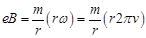
Angular frequency of the electron =  = 2nv
= 2nv
Velocity of the electron is related to the angular frequency as:
v = r
In the circular orbit, the magnetic force on the electron is balanced by the centripetal force. Hence, we can write:

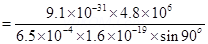
This expression for frequency is independent of the speed of the electron.
On substituting the known values in this expression, we get the frequency as: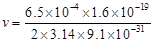


Hence, the frequency of the electron is around 18 MHz and is independent of the speed of the electron.
6. Two concentric circular coils X and Y of radii 16 cm and 10 cm, respectively, lie in the same vertical plane containing the north to south direction. Coil X has 20 turns and carries a current of 16 A; coil Y has 25 turns and carries a current of 18 A. The sense of the current in X is anticlockwise, and clockwise in Y, for an observer looking at the coils facing west. Give the magnitude and direction of the net magnetic field due to the coils at their centre.
Ans. Radius of coil X,  = 0.16 m
Radius of coil Y,  = 0.1 m
Number of turns of on coil X, 
Number of turns of on coil Y, 
Current in coil X, 
Current in coil Y, 
Magnetic field due to coil X at their centre is given by the relation,
Where, = Permeability of free space =
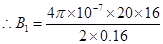
 (towards East)
Magnetic field due to coil Y at their centre is given by the relation, 
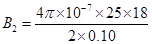
 (towards East)
Hence, net magnetic field can be obtained as:

7. For a circular coil of radius R and N turns carrying current I, the magnitude of the magnetic field at a point on its axis at a distance x from its centre is given by,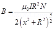
(a) Show that this reduces to the familiar result for field at the centre of the coil.
(b) Consider two parallel co-axial circular coils of equal radius R, and number of turns N, carrying equal currents in the same direction, and separated by a distance R. Show that the field on the axis around the mid-point between the coils is uniform over a distance that is small as compared to R, and is given by, 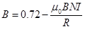 , approximately. [Such an arrangement to produce a nearly uniform magnetic field over a small region is known as Helmholtz coils.]
Ans. Radius of circular coil = R
Number of turns on the coil = N
Current in the coil = I
Magnetic field at a point on its axis at distance x is given by the relation,
Where, = Permeability of free space
(a) If the magnetic field at the centre of the coil is considered, then x = 0.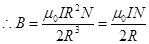
This is the familiar result for magnetic field at the centre of the coil.
(b) Radii of two parallel co-axial circular coils = R
Number of turns on each coil = N
Current in both coils = I
Distance between both the coils = R
Let us consider point Q at distance d from the centre.
Then, one coil is at a distance of  from point Q.Magnetic field at point Q is given as:
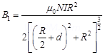
Also, the other coil is at a distance of  from point Q.Magnetic field due to this coil is given as:
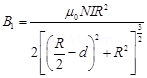
Total magnetic field, 
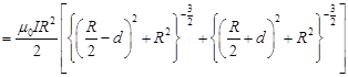
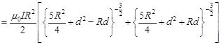
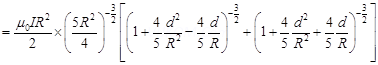
For d << R, neglecting the factor  , we get:
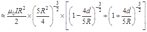
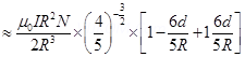
Hence, it is proved that the field on the axis around the mid-point between the coils is uniform.
8. An electron emitted by a heated cathode and accelerated through a potential difference of 2.0 kV, enters a region with uniform magnetic field of 0.15 T. Determine the trajectory of the electron if the field (a) is transverse to its initial velocity, (b) makes an angle of 30º with the initial velocity.
Ans. Magnetic field strength, B = 0.15 T
Charge on the electron,
Mass of the electron, 
Potential difference, V = 2.0 
Thus, kinetic energy of the electron = 

 ……(1)
……(1)
Where,
v = velocity of the electron
(a) Magnetic force on the electron provides the required centripetal force of the electron. Hence, the electron traces a circular path of radius r.
Magnetic force on the electron is given by the relation,
B ev
Centripetal force 

 ……(2)
……(2)
From equations (1) and (2), we get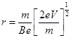
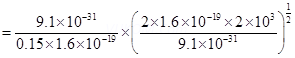


= 1 mm
Hence, the electron has a circular trajectory of radius 1.0 mm normal to the magnetic field.
(b) When the field makes an angle  with initial velocity, the initial velocity will be,
From equation (2), we can write the expression for new radius as: 

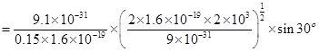

= 0.5 mm
Hence, the electron has a helical trajectory of radius 0.5 mm along the magnetic field direction.
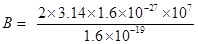
9. A magnetic field set up using Helmholtz coils (described in Exercise 4.16) is uniform in a small region and has a magnitude of 0.75 T. In the same region, a uniform electrostatic field is maintained in a direction normal to the common axis of the coils. A narrow beam of (single species) charged particles all accelerated through 15 kV enters this region in a direction perpendicular to both the axis of the coils and the electrostatic field. If the beam remains undeflected when the electrostatic field is  , make a simple guess as to what the beam contains. Why is the answer not unique?
Ans. Magnetic field, B = 0.75 T
Accelerating voltage, V = 15 
Electrostatic field, E =
Mass of the electron = m
Charge of the electron = e
Velocity of the electron = v
Kinetic energy of the electron = eV
 …… (1)
Since the particle remains unelected by electric and magnetic fields, we can infer that the electric field is balancing the magnetic field.
 ……..(2)
Putting equation (2) in equation (1), we get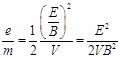
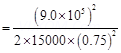

This value of specific charge e/m is equal to the value of deuteron or deuterium ions. This is not a unique answer. Other possible answers are , etc.
10. A uniform magnetic field of 1.5 T exists in a cylindrical region of radius10.0 cm, its direction parallel to the axis along east to west. A wire carrying current of 7.0 A in the north to south direction passes through this region. What is the magnitude and direction of the force on the wire if,
(a) the wire intersects the axis,
(b) the wire is turned from N-S to northeast-northwest direction,
(c) the wire in the N-S direction is lowered from the axis by a distance of 6.0 cm?
Ans.Magnetic field strength, B = 1.5 T
Radius of the cylindrical region, r = 10 cm = 0.1 m
Current in the wire passing through the cylindrical region, I = 7 A
(a) If the wire intersects the axis, then the length of the wire is the diameter of the cylindrical region.
Thus, l = 2r = 0.2 m
Angle between magnetic field and current,
Magnetic force acting on the wire is given by the relation,
F = BIl 
= 
= 2.1 N
Hence, a force of 2.1 N acts on the wire in a vertically downward direction.
(b) New length of the wire after turning it to the Northeast-Northwest direction can be given as:
Angle between magnetic field and current, θ = 45°
Force on the wire,
F = 
= BIl
=2.1 N
Hence, a force of 2.1 N acts vertically downward on the wire. This is independent of angle  because
  is fixed.
(c) The wire is lowered from the axis by distance, d = 6.0 cm
Suppose wire is passing perpendicularly to the axis of cylindrical magnetic field then lowering 6 cm means displacing the wire 6 cm from its initial position towards to end of cross sectional area.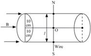

= 8cm
Thus the length of wire in magnetic field will be 16 cm as AB= L =2x =16 cm
Now the force,
F = iLB  as the wire will be perpendicular to the magnetic field.
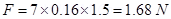 The direction will be given by right hand curl rule or screw rule i.e. vertically downwards.
11. A uniform magnetic field of 3000 G is established along the positive z-direction. A rectangular loop of sides 10 cm and 5 cm carries a current of 12 A. What is the torque on the loop in the different cases shown in Fig. 4.28? What is the force on each case? Which case corresponds to stable equilibrium?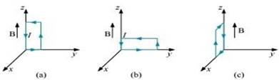
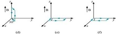
Ans.Magnetic field strength, B = 3000 G =  = 0.3 T
Length of the rectangular loop, l = 10 cm
Width of the rectangular loop, b = 5 cm
Area of the loop, =
=  =
= 
Current in the loop, I = 12 A
Now, taking the anti-clockwise direction of the current as positive and vise-versa:
(a) Torque, 
From the given figure, it can be observed that A is normal to the y–z plane and B is directed along the z-axis.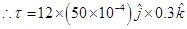

The torque is  along the negative y-direction. The force on the loop is zero because the angle between A and B is zero.
(b) This case is similar to case (a). Hence, the answer is the same as (a).
(c) Torque 
From the given figure, it can be observed that A is normal to the x–z plane and B is directed along the z-axis.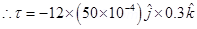

The torque is along the negative x direction and the force is zero.
(d) Magnitude of torque is given as:
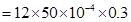
Torque is at an angle of  with positive x direction. The force is zero.
(e) Torque 
= 0
Hence, the torque is zero. The force is also zero.
(f) Torque
= 0
Hence, the torque is zero. The force is also zero.
In case (e), the direction of  and
and  is the same and the angle between them is zero. If displaced, they come back to an equilibrium. Hence, its equilibrium is stable.
Whereas, in case (f), the direction of and is opposite. The angle between them is 180°. If disturbed, it does not come back to its original position. Hence, its equilibrium is unstable.
12. A solenoid 60 cm long and of radius 4.0 cm has 3 layers of windings of 300 turns each. A 2.0 cm long wire of mass 2.5 g lies inside the solenoid (near its centre) normal to its axis; both the wire and the axis of the solenoid are in the horizontal plane. The wire is connected through two leads parallel to the axis of the solenoid to an external battery which supplies a current of 6.0 A in the wire. What value of current (with appropriate sense of circulation) in the windings of the solenoid can support the weight of the wire? 
Ans.Length of the solenoid, L = 60 cm = 0.6 m
Radius of the solenoid, r = 4.0 cm = 0.04 m
It is given that there are 3 layers of windings of 300 turns each.
Total number of turns,  = 900
= 900
Length of the wire, l = 2 cm = 0.02 m
Mass of the wire, m = 2.5 g = 
Current flowing through the wire, i = 6 A
Acceleration due to gravity, 
Magnetic field produced inside the solenoid, 
Where,= Permeability of free space =
I = Current flowing through the windings of the solenoid
Magnetic force is given by the relation, F = Bil
Also, the force on the wire is equal to the weight of the wire.


Hence, the current flowing through the solenoid is 108 A.