Question
In the laboratory, you are given three resistors: \(R_{1}\) = 30 kW, \(R_{2}\) = 60 kW, and \(R_{3}\) = 120 kW. You are to use these three resistors in a circuit with a 12-V battery such that one resistor is in series with the battery, and the other two are parallel with each other.
(a) Diagram a circuit with these three resistors such that the resistor in series with the battery takes the largest possible voltage across it. Justify your answer.
(b) For these three given resistors, is it possible for the resistor in series with the battery to take a smaller voltage than either of the two parallel resistors? Justify your answer.
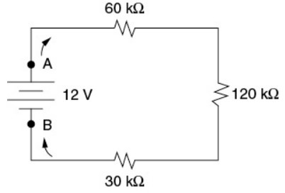
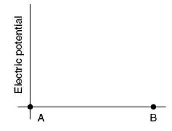
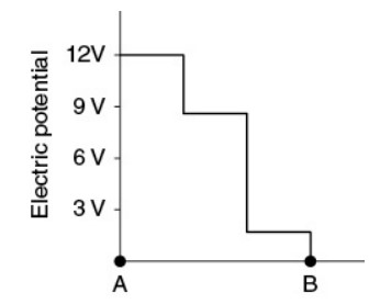
(c) Now the resistors are connected in series with the battery, as shown in the figure. On the axes provided, sketch a graph of the electric potential (V) measured along the circuit, starting at position A, going in the direction shown, and ending at position B. Consider the electric potential at position B to be zero.
▶️Answer/Explanation
Ans:
Part (a)
The resistor in series with the battery takes the largest current of any of the three resistors by Kirchoff’s junction rule. By Ohm’s law, V = IR, a resistor with both the largest current and the largest resistance will similarly take the largest voltage. So put the largest resistor \(R_{3}\) in series with the battery, as shown.
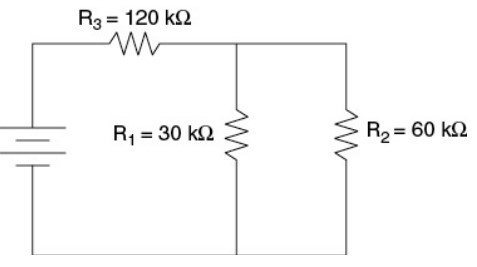
Part (b)
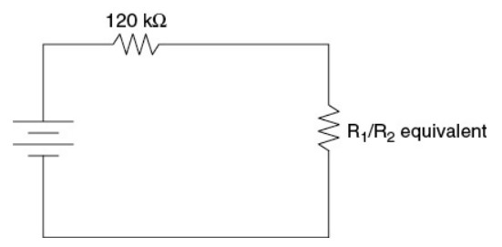
Yes. Consider the equivalent circuit drawn, where the second resistor is the equivalent resistor of the parallel combination. These two resistors each take the same current by Kirchoff’s junction rule; by Ohm’s law, with the same current, the larger of the two takes the larger voltage. If the equivalent resistance of the parallel combination is greater than the resistance of the resistor in series with the battery, then the parallel combination will take more voltage than the first resistor. In this case, putting \(R_{1}\) in series with the battery and the other two resistors in the parallel combination satisfies this condition; the equivalent resistance of \(R_{2}\) and \(R_{3}\) in parallel is greater than 30 kW.
Part (c)
The total resistance of this circuit is the sum of the three resistors, 210 kW. The total current in the circuit is 12 V/210 kW = 57 mA (that is, 0.000057 A). Using that current in V = IR for each resistor gives a voltage drop of 3.4 V, 6.9 V, and 1.7 V across each resistor in turn. So start the graph at 12 V. The voltage drops by 3.4 V after the 60 kW resistor, down to 8.6 V, as shown in the diagram. (The voltage does not change along the wire itself, which has essentially zero resistance compared to the resistors.) When we get to the 120 kW resistor, drop the voltage another 6.9 V, down to 1.7 V left. The voltage drops the rest of the way to zero after the 30 kW resistor, as required by Kirchoff’s loop rule.
Question
(12 points-suggested time 25 minutes)
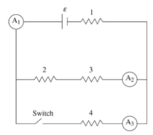
The figure shows a circuit with a battery of emf ε and negligible internal resistance, and four identical resistors of resistance R numbered 1, 2, 3, and 4. There are three ammeters (A1, A2, and A3) that measure the currents I1, I2, and I3, respectively. The circuit also has a switch that begins in the closed position.
(A) A student makes this claim: “The current I3 is twice as large as I2.” Do you agree or disagree with the student’s statement? Support your answer by applying Kirchhoff s loop rule and writing one or more algebraic expressions to support your argument.
(B) Rank the power dissipated into heat by the resistors from highest to lowest, being sure to indicate any that are the same. Justify your ranking.
The switch is opened. A student makes this statement: “The power dissipation of resistors 2 and 3 remains the same because they are in parallel with the switch. The power dissipation of resistor 1 decreases because opening the switch cuts off some of the current going through resistor 1.”
(C) i. Which parts of the student’s statement do you agree? Justify your answer with appropriate physics principles.
ii. Which parts of the student’s statement do you disagree with? Justify your answer utilizing an algebraic argument.
The switch remains open. Resistor 4 is replaced with an uncharged capacitor of capacitance C. The switch is now closed.
(D) i. Determine the current in resistor 1 and the potential difference across the capacitor immediately after the switch is closed.
ii. Determine the current in resistor 1 and the potential difference across the capacitor a long time after the switch is closed.
iii. Calculate the energy CU) stored on the capacitor a long time after the switch is closed.
▶️Answer/Explanation
Ans:
Part (A)
Agree.
1 point-For correctly applying Kirchhoffs loop rule for the upper loop:
ε – I2R – I2R – I1R = 0
ε = 2I2R – I1R
1 point-For correctly applying Kirchhoff’s loop rule to the outer loop:
ε – I3R – I1R = 0
ε = I3R – I1R
1 point-For correctly using the two equations to show that I3 is twice as large as I2:
2I2R – I1R = I3R – I1R
2I2R = I3R
2I2 = I3
Part (B)
No points are awarded for the correct ranking of: P1 > P4 > P2 = P3.
1 point-For indicating that Power= I2R and that all the resistors are the same. Therefore, the ranking is based on the current passing through the resistors.
1 point-For indicating that resistor 1 receives the most current as all the current must pass through it AND that resistor 4 receives more current than resistors 2 and 3 AND that resistors 2 and 3 receive the same current because they are in the same conductive pathway.
Part (C)
(i.) Agree that the power will go down for resistor 1.
1 point-For indicating that when the switch is opened, there is only one path left for the current to pass through. This means the total resistance of the circuit increases. The potential difference across resistor 1 will decrease, which will bring its power dissipation down as well.
(ii.) Disagree that resistors 2 and 3 are unaffected.
1 point-For deriving a correct expression for the original current passing through resistors 2 and 3:
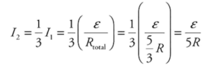
1 point-For deriving a correct expression for the new current passing through resistors 2 and 3:
\(I_{2}=I_{1}=\frac{\varepsilon }{R_{total}}=\frac{\varepsilon }{3R}\)
The new current is larger than the old; therefore, the power dissipation goes up. (Note that this argument can be also be made using potential difference and would also receive credit.)
Part (D)
(i.) Immediately after the switch is closed, the capacitor acts like a short-circuit wire that allows the current to bypass resistors 2 and 3.
1 point-For indicating that the current through resistor 1 will be \(I_{1}=\frac{\varepsilon }{R},\) and that the potential difference across the capacitor is zero (ΔVC =0).
(ii.) After a long period of time, the capacitor becomes fully charged and acts like an open switch in the circuit.
1 point-For indicating the current through resistor 1 will be: \(I_{1}=\frac{\varepsilon }{3R}.\)
1 point-For indicating that the potential difference across the capacitor will be equal to that of resistors 2 and 3 combined, because the capacitor is in parallel with them: \(\Delta V_{C}=\frac{2}{3}\varepsilon .\) Note this can be stated in words or symbolically to receive credit.
(iii.)
1 point-For calculating the potential energy stored by the capacitor: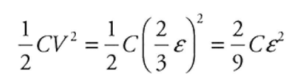
Question
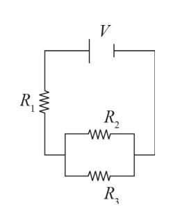
The above circuit contains a battery of voltage V and three resistors with resistances \(R_{1}\), \(R_{2}\), and \(R_{3}\), respectively. As part of an experiment, a student has been given two measuring devices: a voltmeter and an ammeter. The first can be used to measure the changes in voltage of a circuit. The second can be used to measure the current flowing through a particular segment of wire. For answering the questions below, a voltmeter and ammeter look like ![]() and
and ![]() , respectively, when drawn in a circuit diagram.
, respectively, when drawn in a circuit diagram.
(a) In terms of the known variables, what is the voltage lost in passing through the first resistor?
(b) Draw a diagram showing how you would integrate the voltmeter to measure the voltage lost in the resistor labeled \(R_{1}\). Explain the reasoning behind your decision.
(c) Draw a diagram showing how you would integrate the ammeter to measure the current passing through the resistor labeled \(R_{1}\). Explain the reasoning behind your decision.
(d) What would be the ideal resistances for each device to have? Explain why each would be ideal for that device.
▶️Answer/Explanation
Ans:
(a) First, find the equivalent resistance for the whole circuit. First, the total resistance of the two parallel resistors can be found by using \(\frac{1}{R_{T}}=\frac{1}{R_{2}}+\frac{1}{R_{3}}=\frac{R_{2}+R_{3}}{R_{2}R_{3}}\), which means \(R_{T}=\frac{R_{2}R_{3}}{R_{2}+R_{3}}\). Then this would be in series with the first resistor, so the equivalent resistance of the whole circuit, \(R_{eq}\), would be \(R_{eq}=\frac{R^{1}+R_{2}R_{3}}{R_{2}+R_{3}}=\frac{R_{1}R_{2}+R_{1}R_{3}+R_{2}R_{3}}{R_{2}+R_{3}}\)
Next, we know from Ohm’s Law that V = IR, so you can say \(I=V/R=\frac{V}{\frac{R_{1}R_{2}+R_{1}R_{3}+R_{2}R_{3}}{R_{2}+R_{3}}}=\frac{V(R_{2}+R_{3})}{R_{1}R_{2}+R_{1}R_{3}+R_{2}R_{3}}\). This will be the total current of the circuit. Because there are no branches before R1, this will also be the current flowing through that resistor. So the voltage drop of that resistor, V1, can be found by again using Ohm’s Law for that location rather than the whole resistor. This gives \(V_{1}=I_{1}R_{1}=\frac{V(R_{2}+R_{3})}{R_{1}R_{2}+R_{1}R_{3}+R_{2}R_{3}}R_{1}\).
(b) The diagram should look like this:
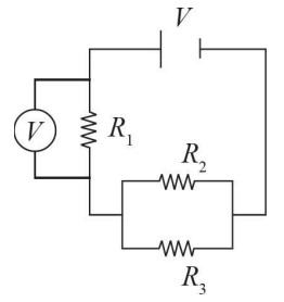
In order to measure the voltage loss of a particular resistor, the voltmeter must be arranged in parallel with that resistor. This is because parallel elements always have equal voltage drops. Thus, whatever voltage drop the device measures will be the same as the voltage drop in the resistor being measured.
(c) The diagram should look like this:
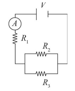
In order to measure the current passing through a particular resistor, the ammeter must be arranged in series with that resistor. This is because elements in series always have equal currents. Thus, whatever current the device measures will be the same as the current flowing through the resistor being measured.
(d) For the voltmeter, infinite resistance would be ideal. As in all measurements, you don’t want to disturb the system in any way as you take the measurement. Otherwise, your readings would not be accurate for the original system. Thus, in order to leave the circuit as it was, we need to maintain the flow of current that exists before we started our measurement. Having an infinite resistance would ensure no current flows into the voltmeter, leaving it all on its original path.
For the ammeter, 0 resistance would be ideal. Again, we want to have minimal disturbance on the system. If the ammeter did have resistance, then it would be a source of voltage loss that did not previously exist. In essence, it would be an additional resistor that would need to considered, forcing us to recalculate everything from the ground up.