Focus Question: How does a capacitor work in a circuit?
Answer/Explanation
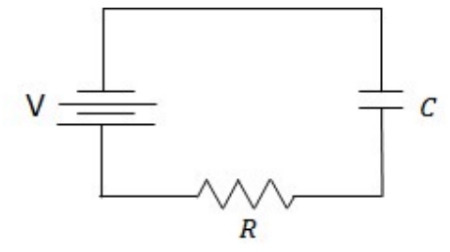
- Electrons leaves the negative terminal of the battery and flow to the upper plate of the capacitor. The electrons on the upper plate of the capacitor repel electrons from the lower plate, so those electrons flow through the resistor to the battery.
- Charge flows in the capacitor until the voltage in the capacitor equals $\mathrm{V}$, then no more current flows in the circuit.
Charging capacitor – The charge on the capacitor is initially zero.
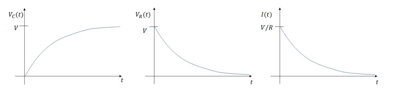
- Voltage across the resistor: $V_R(t)$ starts at the $\mathrm{V}$ (battery voltage) and decays to zero.
- Current, dq/dt, starts at $\mathrm{V} / R$ and decays to 0 .
- Voltage across the capacitor: $V_C(t)$ starts 0 (acts like a wire) and ends at $V$ (acts like a short circuit)
By Kirchoff’s Law:
$
\begin{aligned}
& V-V_R-V_c=0 \\
& V-I R-\frac{q}{C}=0 \rightarrow V=\frac{d q}{d t} R+\frac{q}{C}=0 \\
& \rightarrow C V=\frac{d q}{d t} R C+q \rightarrow-\frac{d q}{d t} R C=q-C V
\end{aligned}
$
Separating the variables: $\frac{d q}{q-C V}=-d t \frac{1}{R C}$
The charge on the capacitor goes from 0 to the charge at some time, $\mathrm{Q}(\mathrm{t})$.
$
\begin{aligned}
& \int_0^{Q(t)} \frac{d q}{q-C V}=\int_0^t-\frac{1}{R C} d t \\
& \ln |q-C V|^{Q(t)}=-\frac{t}{R C} \\
& \ln |Q(t)-C V|-\ln |-C V|=-\frac{t}{R C} \rightarrow \ln \left|\frac{Q(t)-C V}{-C V}\right|=-\frac{t}{R C} \\
& \frac{Q(t)-C V}{-C V}=e^{-\frac{t}{R C}} \rightarrow Q(t)=C V\left(1-e^{-\frac{t}{R C}}\right)
\end{aligned}
$
Dividing the result by the capacitance, the voltage across the capacitance as a function of time can be found: $\boldsymbol{V}_C(\boldsymbol{t})=\boldsymbol{V}\left(\mathbf{1}-e^{-\frac{t}{R C}}\right)$
This is also commonly written as $V_C(t)=V\left(1-e^{-\frac{t}{\tau}}\right)$, where $\tau$ is the time constant, where $\boldsymbol{\tau}=\boldsymbol{R} \boldsymbol{C}$.
The voltage in the resistor acts opposite the capacitor as it drops to zero by the opposite function: $V_R(t)=V e^{-\frac{t}{R C}}$
The current also drops to zero: $\boldsymbol{I}(t)=\frac{V}{R} e^{-\frac{t}{R C}}$
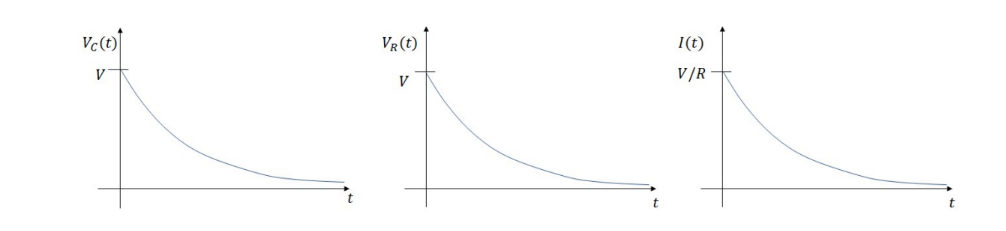
Graphs for to charging circuit:
Example A: Power is supplied to the circuit on the right
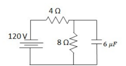
a) What steady current flows in the circuit on the right through the 4 ohm resistor? Justify your answer?
b) What is the charge stored in the capacitor?
Answer/Explanation
a) At steady state, current simply stops flowing through the branch with the capacitor, so the circuit will be a simple loop through the two resistors.
$
I=\frac{120 \mathrm{~V}}{4 \Omega+8 \Omega}=\mathbf{1 0} \mathrm{A}
$
b) The capacitor is in parallel with the $8 \mathrm{ohm}$ resistor, so it will only have the voltage of that resistor.
The voltage of the $8 \mathrm{ohm}$ capacitor is $120 \mathrm{~V}\left(\frac{8 \Omega}{4 \Omega+8 \Omega}\right)=80 \mathrm{~V}$
$
U=\frac{1}{2} C V^2=\frac{1}{2}\left(6 \times 10^{-6} F\right)(80 V)^2=. \mathbf{0 2} \mathrm{J}
$
Discharging Circuit – Suppose the switch in the RC circuit is left closed for a long time and then opened.
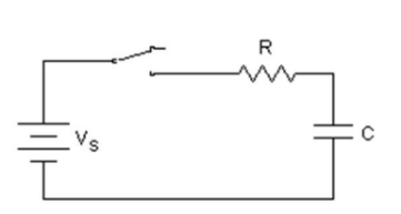
- $V_R(t)$ : starts at the $V_C$ and decays to zero.
- Current, dq/dt, starts at $V_C / R$ and decays to 0 .
- $V_C(t)$ : starts at $V_C$ and decays to zero.
By Kirchoff’s Law:
$
\begin{aligned}
& V_c+V_R=0 \\
& \frac{q}{C}+\frac{d q}{d t} R=0 \rightarrow \frac{q}{R C}=-\frac{d q}{d t}
\end{aligned}
$
Separating the variables: $\frac{d q}{q}=-\frac{1}{R C} d t$
The charge on the capacitor starts at its maximum value, $\mathrm{Q}$, and goes to $\mathrm{Q}(\mathrm{t}): \quad \int_Q^{Q(t)} \frac{d q}{q}=\int_0^t-\frac{1}{R C} d t$
$
\rightarrow \ln |q|^{Q(t)}=-\frac{t}{R C} \rightarrow \ln |Q(t)|-\ln |Q|=-\frac{t}{R C} \rightarrow \ln \left|\frac{Q(t)}{Q}\right|=-\frac{t}{R C} \rightarrow \frac{Q(t)}{Q}=e^{-\frac{t}{R C}} \rightarrow Q(t)=Q e^{-\frac{t}{R C}}
$
The voltage across the capacitor is then $V_C(t)=V e^{-\frac{t}{R C}}$
The capacitor acts as the battery for the resistor, so $V_R(t)=V e^{-\frac{t}{R C}}$
The current also drops asymptotically to zero: $I(t)=\frac{V}{R} e^{-\frac{t}{R C}}$
Graphs for to discharging circuit:
Example B: A circuit with a $9 \mathrm{~V}$ battery of negligible internal resistance is set up with 2 resistors in series with a $10 \mu F$ capacitor. Two switches exist in the circuit.
a) $S_1$ is closed at time $t=0 \mathrm{~s}$. $S_2$ is kept open.
i. Calculate the time constant.
ii. Calculate the time it would take the capacitor to reach a potential differenct of $6 \mathrm{~V}$
b) Once the capactior is fully charged, $\mathrm{S}_2$ is closed. $\mathrm{S}_1$ is opened.
i. Calculate the new constant.
ii. Find the current in the $1 \mathrm{k} \Omega$ as a function of time.
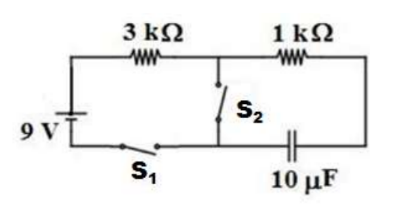
Answer/Explanation
a) i. The time constant is based only on the resistors directly in series with the capacitor, in this, both resistors are in series with the resistor.
$
\begin{aligned}
& \text { ii. } V_c(t)=V\left(1-e^{-t / \tau)} \tau=R C=(3000 \Omega+1000 \Omega)\left(10 \times 10^{-10} F\right)=4 \times 10^{-6} \Omega F\right. \\
& \rightarrow 6 V=(12 V)\left(1-e^{-\frac{t}{4 \times 10^{-6} \Omega F}}\right) \\
& \rightarrow 0.5=e^{-\frac{t}{4 \times 10^{-6}}} \rightarrow \ln |.5|=-\frac{t}{4 \times 10^{-6}} \rightarrow t=-\left(4 \times 10^{-6}\right) \ln |.5|=2.8 \times 10^{-6} \mathrm{~s}
\end{aligned}
$
b) i. Now, only the $1 \mathrm{k} \Omega$ resistor is in series with the capacitor.
$
\tau=R C=(1000 \Omega)\left(10 \times 10^{-1} F\right)=1 \times 10^{-6} \Omega F
$
ii. Even though only the $\mathrm{k} \Omega$ resistor is used for the time constant, the starting current is based on the steadystate current when both resistors were in series:
$
\begin{aligned}
& I(t)=\frac{V}{R} e^{-\frac{t}{\tau}} \rightarrow I(t)=\frac{9 V}{4000 \Omega} e^{-\frac{t}{1 \times 10^{-6}}} \\
& I(t)=.00225 e^{-1000000 t}
\end{aligned}
$
Example C: Here’s a physics problem. V $=100$ volts; $C_1=12$ microfarads; $\mathrm{C}_2=24$ microfarads; $\mathrm{R}=10$ ohms. Initially, $\mathrm{C}_1$ and $\mathrm{C}_2$ are uncharged, and all switches are open.
a) First, switch $S_1$ is closed. Determine the charge on $C_1$ when equilibrium is reached.
b) Next $S_1$ is opened and afterward $S_2$ is closed. Determine the charge on $\mathrm{C}_1$ when equilibrium is again reached.
c) For the equilibrium condition of part (b), determine the voltage across $C_1$.
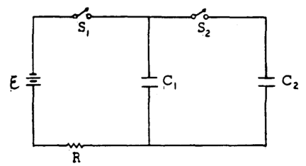
Answer/Explanation
a) The total charge once $C_1$ is charged is $Q=C_1 \varepsilon=\left(12 \times 10^{-6}\right)(100 \mathrm{~V})=\mathbf{1 . 2} \boldsymbol{m C}$
b) At equilibrium the voltage on each is equal.
$
\begin{gathered}
V_1=V_2 \rightarrow \frac{Q_1}{C_1}=\frac{Q_2}{C_2} \rightarrow \frac{Q_1}{12 \mu F}=\frac{Q_2}{24 \mu F} \\
\rightarrow Q_2=2 Q_1
\end{gathered}
$
The $1.2 \mathrm{mC}$ charge is split between the capacitors:
$
Q_1+Q_2=1.2 x 10^{-3} C
$
Solving the system: $Q_1=4 x 10^{-4} C, Q_2=8 x 10^{-4} C$
c) $V=\frac{Q_1}{C_1}=\frac{4 x 10^{-4} \mathrm{C}}{12{ }^{-6} \mathrm{~F}}=33 \mathrm{~V}$
d) The energy initially stored in $\mathrm{C}_1$ is: $U=\frac{1}{2}\left(12 x 10^{-6}\right)(100 \mathrm{~V})^2=.06 \mathrm{~J}$
The energy in $C_1$ after steady state: $U_1=\frac{1}{2}\left(12 \times 10^{-6}\right)(33 \mathrm{~V})^2=.013 \mathrm{~J}$
The energy in $\mathrm{C}_2$ after steady state: $U_2=\frac{1}{2}\left(24 \times 10^{-6}\right)(33 \mathrm{~V})^2=.013 \mathrm{~J}$
Energy lost $=.06 \mathrm{~J}-(.013 \mathrm{~J}+.013 \mathrm{~J})$