Question
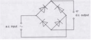
(a) Alternating current (a.c.) is converted into direct current (d.c.) using a full-wave rectification circuit. Part of the diagram of this circuit is shown in Fig. 7.1.
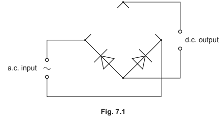
(i) Complete the circuit in Fig. 7.1 by adding the necessary components in the gaps.
(ii) On Fig. 7.1 mark with a + the positive output terminal of the rectifier.
(b) The output voltage V of an a.c. power supply varies sinusoidally with time t as shown in Fig. 7.2.
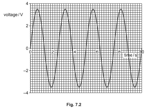
(i) Determine the equation for V in terms of t, where V is in volts and t is in seconds.
(ii) The supply is connected to a \(12\) Ω resistor. Calculate the mean power dissipated in the resistor.
Answer/Explanation
Ans:
(a) (i) two diodes added in correct directions (Both diodes pointing inwards and upwards), correct symbols only
(ii) ‘+’ anywhere on upper output wire
(b) (i) \(ω\) = \(2π / T\)
= \(2π / 2.5\)
= \(0.80 π\) or \(4 π / 5\) or \(2.5\)
\((V =)\) \(3.5 \sin (0.8 π t)\) or \(3.5 \sin (4 π t / 5)\) or \(3.5 \sin (2.5 t)\)
(ii) \((P =) \frac{V^{2}}{2R}\) or \((P=) \frac{V_{r.m.s^{2}}}{R}\)
= \(\frac{3.5^{2}}{2\times 12}\) or \(\frac{2.47^{2}}{12}\)
Question
(a) State, by reference to the power dissipated in a resistor, what is meant by the root-mean-square (r.m.s.) value of an alternating voltage. [2]
(b) A coil is rotating freely, on frictionless bearings, at constant speed in a uniform magnetic field. This rotation causes an induced alternating electromotive force (e.m.f.) across the open terminals of the coil. The induced e.m.f. has r.m.s. value 12V and frequency 50Hz. The speed of rotation of the coil is now doubled.
(i) State and explain, with reference to the principles of electromagnetic induction, the effect of the increased speed of rotation on the r.m.s. value of the induced e.m.f. [2]
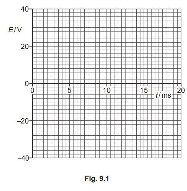
(ii) On Fig. 9.1, sketch the variation with time t of the induced e.m.f. E across the terminals of the coil at the increased speed of rotation. Your line should extend from time t = 0 to time t = 20ms. Assume that E = 0 when t = 0.
(c) State and explain the effect on the motion of the coil in (b) of connecting a load resistor across its terminals. [2]
[Total: 9]
Answer/Explanation
Ans
(a) constant voltage
that produces/dissipates same power as (the mean power of) the alternating voltage
(b) (i) (maximum) rate of cutting of (magnetic) flux doubles
(peak and hence) r.m.s. induced e.m.f. doubles
(b) (ii) sketch: (sinusoidal) wave of period 10 ms
peak E shown as ± 34V
(1 mark out of 2 awarded if peak E shown as ± 17 V or ± 24V)
(c) current in the coil results in forces that oppose its rotation
or
current in the resistor dissipates the energy of rotation