Kirchhoff’s First Law
• Kirchhoff’s First Law: At any junction in a circuit, the sum of the currents arriving at the junction is equal to the sum of the currents leaving the junction.
• This is also known as ‘junction rule’.
Conservation of Charge and the Kirchhoff’s First Law
Kirchhoff’s first rule is a statement of conservation of electric charge.
- All charges that enter a given point in a circuit must leave that point because charge cannot build up (accumulate) at a point.
- If this does not happen then charges are getting accumulated at a point or charges are created from nowhere! both of which don’t happen, In other words – charge is conserved.
The sum of currents meeting at a Junction
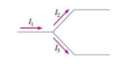
Figure : Current $I_1$ splits into $I_2$ and $I_3$
If we apply this rule to the junction shown in Figure below , we obtain
$
I_1=I_2+I_3
$
The law can also be stated as:-The algebraic sum of currents meeting at a junction is zero.
SIGN CONVENTION USED: Currents entering a Junction are taken as positive and currents leaving a junction is taken as negative.
Example:- Consider a junction O in an electrical circuit as show below:- Here the currents $I_1$; and;
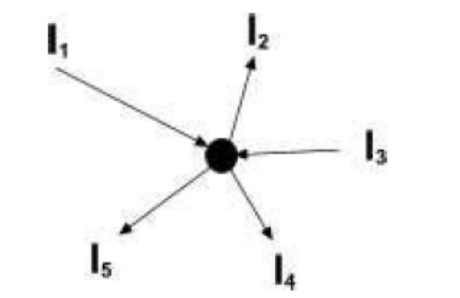
Figure : Currents entering a Junction are taken as positive and currents leaving a junction is taken as negative.
$I_3$ are entering the junction $\mathrm{O}$ whereas $I_2, I_4$ and $I_5$ leave the junction hence $I_1, I_3$ are positive and $I_2$, $I_4$ and $I_5$ are negative as the are leaving the junction.
Applying the sign convention we get
$
I_1+I_3-I_2-I_4-I_5=0
$
or
$
\begin{gathered}
I_1+I_3=I_2+I_4+I_5 \\
\text { (current in =current out) }
\end{gathered}
$
Conservation of charge (must know in order to solve circuit problems)
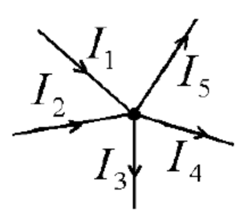
Given that we are dealing with steady currents (i.e. no accumulation of charge at circuit junctions), the sum of currents entering a circuit junction is equal to the sum of currents leaving it.
$
I_1+I_2=I_3+I_4+I_5
$
Taking currents entering circuit junction as positive and currents leaving circuit junction as negative, we have:
$
I_1+I_2-I_3-I_4-I_5=0
$
Taking currents leaving circuit junction as positive and currents entering circuit junction as negative, we have:
$
I_3+I_4+I_5-I_1-I_2=0
$
Sample problem 1
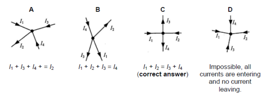
The given diagrams show wires carrying currents $I_1, I_2, I_3$, and $I_4$, meeting at a junction. Which of the following diagrams represents the equation $I_1+I_2=I_3+I_4$ ?
Answer/Explanation
The algebraic sum of e.m.f. (i.e. sources of electrical energy) is equal to the algebraic sum of p.d. (i.e. sinks of energy) for any closed loop within the circuit.
Sample problem 2
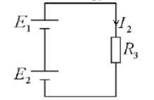
Find $I_1$ and $I_2$ in terms of $E_1, E_2, R_1, R_2$ and $R_3$.
Given that
$
\begin{aligned}
& E_1=3.0 \mathrm{~V} \\
& E_2=1.5 \mathrm{~V} \\
& R_1=R_2=R_3=10 \Omega
\end{aligned}
$
find the values of $I_1$ and $I_2$.
$
\begin{gathered}
E_1+E_2=l_1 R_1+l_1 R_2=l_1\left(R_1+R_2\right) \\
l_1=\frac{E_1+E_2}{R_1+R_2}
\end{gathered}
$
$
\begin{aligned}
& E_1+E_2=I_2 R_3 \\
& I_2=\frac{E_1+E_2}{R_3}
\end{aligned}
$
Solution:
Conservation of energy for the loop:
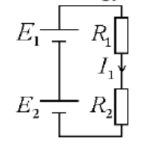
Conservation of energy for the loop:
$\begin{gathered}E_1+E_2=I_1 R_1+I_1 R_2=I_1\left(R_1+R_2\right) \\ l_1=\frac{E_1+E_2}{R_1+R_2}\end{gathered}$
$\begin{aligned} & E_1+E_2=I_2 R_3 \\ & I_2=\frac{E_1+E_2}{R_3}\end{aligned}$
Substituting $E_1=3.0 \mathrm{~V}, E_2=1.5 \mathrm{~V}$ and $R_1=R_2=R_3=10 \Omega$, $I_1=0.23 \mathrm{~A}$ and $I_2=0.45 \mathrm{~A}$.
Kirchhoff’s Second Law
• Kirchhoff’s Second Law: The algebraic sum of e.m.f is equal to the algebraic sum p.d for any closed loop within the circuit.
• This is also known as ‘Loop rule’.
Conservation of Energy and the Kirchhoff’s Second Law
- Kirchhoff’s second rule follows from the law of conservation of energy.
- Let us imagine moving a charge around a closed loop of a circuit. When the charge returns to the starting point, the charge circuit system must have the same total energy as it had before the charge was moved.
- The sum of the increases in energy as the charge passes through some circuit elements must equal the sum of the decreases in energy as it passes through other elements.
- The potential energy decreases whenever the charge moves through a potential drop -IR across a resistor or whenever it moves in the reverse direction through a source of emf.
- The potential energy increases whenever the charge passes through a battery from the negative terminal to the positive terminal.
Rules for applying Kirchoff’s Laws for solving problems
- Currents are labeled with the assumed sense of direction.
- The solution is carried out with the assumed sense of direction and if the actual direction of a particular current is opposite to the assumed direction the value of current will emerge with a negative sign.
- Choose any closed loop in the given network and designate a direction (clockwise or anticlockwise) to traverse the loop for applying the Kirchhoff’s II law.
- Go around the loop in the designated direction algebraically adding the potential differences across the resistors (IR Terms) and the source (cells) emf’s.
- SIGNS: If a resistor is traversed positive first (the end at which the current enters a resistor is positive) then the $I R$ term is taken as negative, similarly for an emf source (say battery) if the positive is encountered first then the emf is taken as negative.
- in order to solve a particular circuit problem, the number of independent equations you need to obtain from the two rules equals the number of unknown currents.
Sample problem 3
Find the currents $I_1, I_2$, and $I_3$ in the circuit shown in Figure 4 below .
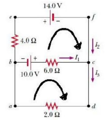
Figure 4: Example Problem
- Arbitrarily choose the directions of the currents as labeled in Figure 4
- Applying Kirchhoffs junction rule to junction $c$ gives
$
I_1+I_2=I_3
$
- We now have one equation with three unknowns $I_1, I_2$, and $I_3$.
- There are three loops in the circuit abcda, befcb, and aefda.
- Applying Kirchhoffs loop rule to loops abcda and befcb and traversing these loops clockwise (shown by curved arrows), we obtain the expressions for the closed loop abcda
$
10.0 \mathrm{~V}-(6.0 \Omega) I_1-(2.0 \Omega) I_3=0
$
for the closed loop befcb
$
14.0 \mathrm{~V}+(6.0 \Omega) I_1-10.0 \mathrm{~V}-(4.0 \Omega) I_2=0
$
which gives
$
(6.0 \Omega) I_1-(4.0 \Omega) I_2=24.0 \mathrm{~V}
$
- Substituting into Equation $I_1+I_2=I_3$ in the equation (2) we get
$
10.0 \mathrm{~V}-(6.0 \Omega) I_1-(2.0 \Omega)\left(I_1+I_2\right)=0
$
which gives
$
10.0 \mathrm{~V}=(8.0 \Omega) I_1+(2.0 \Omega) I_2
$
- solving equations (3) and (4) we get
$
\begin{gathered}
I_1=2.0 \mathrm{~A} \\
I_2=-3.0 \mathrm{~A} \\
I_3=-1.0 \mathrm{~A}
\end{gathered}
$
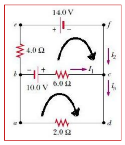
- To finalize the problem, note that $I_2$ and $I_3$ are both negative. This indicates only that the currents are opposite the direction we chose for them. However, the numerical values are correct.
