1. Waves Transfer Energy Without Transferring Matter
![]()
- Waves are disturbances that carry energy from one point to another.
- They do this without transferring matter between points.
- The particles of the medium (air, water, rope, etc.) simply vibrate around a fixed position – they do not travel with the wave.
Example: When you shout across a room, sound energy travels to the other person, but the air molecules themselves don’t move across the room – they only vibrate in place.
2. Wave Motion and Vibrations in Ropes, Springs, and Water
A. Rope or String (Transverse Waves):
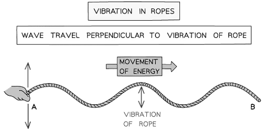
- If you move one end of a rope up and down, a wave travels along the rope horizontally.
- The particles of the rope move perpendicularly to the direction of the wave – this is called a transverse wave.
Example: Flicking a rope attached to a wall shows wave pulses moving forward, but the rope itself only moves up and down.
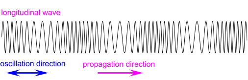
B. Spring or Slinky (Longitudinal Waves):
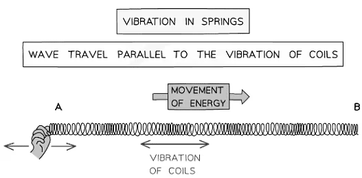
- If you push and pull one end of a stretched spring, regions of compression and rarefaction move along its length.
- The particles of the spring move parallel to the direction of the wave – this is a longitudinal wave.
Example: A push-pull motion on a slinky creates compressions that move along the spring, while coils only oscillate back and forth.
C. Water Surface Waves (Both Transverse and Circular Motion):
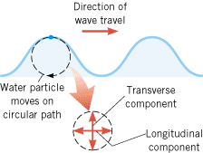
- In water waves, the surface particles move in a circular motion – a combination of up-down and back-forth.
- Energy moves forward across the water, but the water itself does not move forward – it just oscillates in place.
Example: If you drop a stone into still water, ripples move outward, but a floating object (like a leaf) only bobs up and down, showing no net horizontal movement.
Example:
A floating cork is placed on the surface of a water tank. Waves are generated at one end of the tank using a paddle. After several waves pass, the cork is still in nearly the same place, just bobbing up and down.
Explain what this observation tells you about wave motion and how energy is transferred by the wave.
▶️ Answer/Explanation
The cork only moves vertically (up and down), which shows that the particles of the medium (water) do not move along with the wave.
This demonstrates that waves transfer energy — not matter — across the tank.
The energy moves forward through the water (as the wave travels), but the water molecules and the cork stay in approximately the same place, only oscillating around fixed positions.
Conclusion: This proves the principle that waves transfer energy without transferring matter — a key idea in wave motion.
Features of a Wave
![]()
Wavefront:
A wavefront is a line connecting all points on a wave that are at the same phase — e.g., all crests. It shows the direction of energy transfer.
Wavelength (λ):
The distance between two identical points on adjacent waves — such as crest to crest or trough to trough. Measured in metres (m).
Crest (or Peak):
The highest point of a transverse wave above the rest position.
Trough:
The lowest point of a transverse wave below the rest position.
Amplitude:
The maximum displacement of particles from the rest position. It shows how much energy the wave carries. Larger amplitude = more energy.
Frequency (f):
The number of waves passing a point per second. Measured in hertz (Hz).
Wave Speed (v):
The speed at which the wave energy moves through the medium. Measured in metres per second (m/s).
Wave Speed Equation:
\( v = f \times \lambda \)
- \( v \): wave speed in m/s
- \( f \): frequency in Hz
- \( \lambda \): wavelength in metres
Example:
A water wave in a ripple tank has a frequency of 5 Hz and a wavelength of 0.4 m. Calculate the wave speed. Also, identify the crest, trough, and wavelength on the wave diagram shown.
▶️ Answer/Explanation
Use the wave speed formula:
\( v = f \times \lambda = 5 \times 0.4 = \boxed{2.0 \ \text{m/s}} \)
Crest is the highest point of the wave, and the trough is the lowest. The distance between two adjacent crests (or troughs) is the wavelength, which is 0.4 m in this case.
Conclusion: The wave travels at 2.0 m/s, and its structure can be described using features like crest, trough, and wavelength.
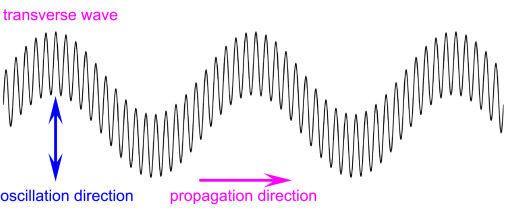
Transverse Waves:
In a transverse wave, the particles (or field disturbances) vibrate at right angles (perpendicular) to the direction in which the wave travels (propagates).
- The crests and troughs are characteristic features of transverse waves.
- Energy moves forward, but the medium moves up and down.
Examples of Transverse Waves:
- Electromagnetic radiation (e.g. light, radio waves, microwaves)
- Water waves on the surface of a pond
- Seismic S-waves (secondary earthquake waves)
Note: Transverse waves can travel through solids and vacuums (EM waves), but not through fluids (for S-waves).
A long rope is attached to a wall. A student flicks the free end of the rope up and down rapidly. The waves travel along the rope horizontally.
Give the direction of vibration and the direction of wave propagation. Identify the type of wave.
▶️ Answer/Explanation
The rope moves up and down — this is the direction of vibration.
The wave pulse moves horizontally along the rope — this is the direction of propagation.
Since the vibration is at right angles to the wave direction, this is a transverse wave.
Conclusion: In transverse waves, the vibration is perpendicular to wave motion — as in ropes, light, water waves, and seismic S-waves.
Longitudinal Waves:
In a longitudinal wave, the particles of the medium vibrate parallel to the direction in which the wave travels (propagates).
- The wave consists of regions of compression (particles close together) and rarefaction (particles far apart).
- There are no crests or troughs in longitudinal waves.
Examples of Longitudinal Waves:
- Sound waves in air or other materials
- Seismic P-waves (primary earthquake waves)
- Compression waves in a stretched spring or slinky
Note: Longitudinal waves require a medium (solid, liquid, or gas) – they cannot travel through a vacuum.
A student pushes and pulls one end of a stretched slinky along the length of the table. A series of compressions and rarefactions travel along the spring.
Describe the direction of particle vibration and wave propagation. Identify the type of wave.
▶️ Answer/Explanation
The coils of the slinky vibrate back and forth in the same direction as the wave travels — both are along the length of the slinky.
This is the defining feature of a longitudinal wave.
Regions of compression and rarefaction are clearly seen as the disturbance moves along the spring.
Conclusion: In longitudinal waves, the vibration is parallel to the wave direction — as seen in sound waves and seismic P-waves.
| Feature | Transverse Wave | Longitudinal Wave |
|---|---|---|
| Direction of vibration | Perpendicular to wave direction | Parallel to wave direction |
| Wave structure | Crests and troughs | Compressions and rarefactions |
| Can travel through vacuum? | Yes (e.g. light) | No – needs a medium |
| Examples | Light, water waves, S-waves | Sound, P-waves, slinky push |
Wave Behaviours
(a) Reflection at a Plane Surface
When a wave hits a flat (plane) surface, it bounces back – this is called reflection.
- The angle of incidence is equal to the angle of reflection.
- This follows the law: angle in = angle out.
- There is no change in speed, wavelength, or frequency – only the wave direction changes.
Example: Light reflecting off a mirror, or a water wave bouncing off a tank wall.
(b) Refraction Due to a Change of Speed
Refraction occurs when a wave passes from one medium to another (e.g. air to glass).
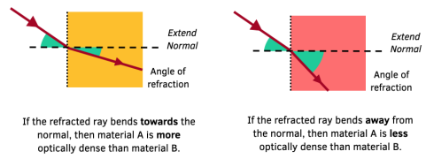
- The wave changes speed, which causes a change in direction (unless it enters at 90°).
- When a wave enters a denser medium, it slows down and bends toward the normal.
- When it enters a less dense medium, it speeds up and bends away from the normal.
- The wavelength changes, but the frequency stays the same.
Example: A straw appearing bent in a glass of water due to light slowing down in water.
(c) Diffraction Through a Narrow Gap
Diffraction is the spreading of waves when they pass through a gap or around an obstacle.
- The wave bends outward after passing through the gap.
- There is no change in wave speed, frequency, or wavelength.
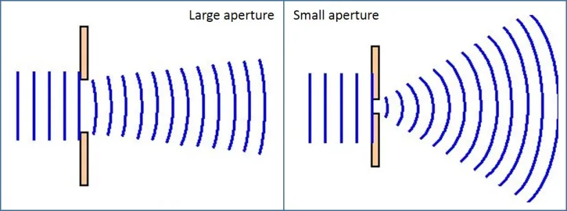
Effect of Wavelength and Gap Size:
- Maximum diffraction occurs when the wavelength ≈ gap width.
- If the gap is much larger than the wavelength: very little diffraction, waves mostly go straight.
- If the gap is similar to or smaller than the wavelength: strong spreading of the wavefront.
Example: Water waves spreading out after passing through a narrow opening in a tank wall.
Example:
A student shines a ray of light at a flat mirror at an angle of 30° to the normal. The light reflects off the surface. What is the angle of reflection and what happens to the speed of the wave?
▶️ Answer/Explanation
By the law of reflection, the angle of reflection is also 30°.
Since the wave stays in the same medium (air), its speed, frequency, and wavelength remain unchanged.
Conclusion: In reflection at a plane surface, angle of incidence = angle of reflection, and wave properties do not change.
Example:
A light ray passes from air into a glass block at an angle. It bends toward the normal line. Explain why the light ray bends, and what happens to its speed and wavelength.
▶️ Answer/Explanation
Glass is denser than air, so the light wave slows down as it enters.
This causes the wave to bend toward the normal.
The speed and wavelength decrease, but the frequency remains the same.
Conclusion: Refraction is caused by a change in speed, leading to a change in direction and wavelength (but not frequency).
Example:
Water waves approach a barrier with a small gap. After passing through, the wave spreads out in semicircles. Explain why the waves spread out, and how the gap size affects the spreading.
▶️ Answer/Explanation
The wave spreads due to diffraction a wave effect that happens when waves pass through a gap or around an obstacle.
Maximum diffraction occurs when the wavelength is approximately equal to the gap size.
If the gap is much larger than the wavelength, little spreading occurs.
Conclusion: Diffraction causes waves to spread out. It is strongest when the gap size is similar to the wavelength.
Using a Ripple Tank to Demonstrate Wave Behaviours

(a) Reflection at a Plane Surface
- Place a flat barrier (like a metal strip) in the ripple tank at an angle to the wavefronts.
- Switch on the vibrator to produce straight water waves (plane wavefronts).
- Observe how the waves reflect off the barrier – the angle of reflection equals the angle of incidence.
- Wavelength and speed remain the same; only the direction changes.
Observation: Reflected wavefronts form at the same angle to the barrier as the incident wavefronts.
Example:
In a ripple tank, waves are directed toward a flat metal barrier at an angle of 40° to the normal. The reflected wavefronts are seen leaving at the same angle.
Why don’t the wave speed or wavelength change after reflection?
▶️ Answer/Explanation
The waves remain in the same medium (water), so the wave speed and wavelength do not change. Only the direction of the wavefronts changes according to the law of reflection.
(b) Refraction Due to a Change in Speed (Caused by Depth Change)
- Place a transparent plastic sheet or glass block in part of the ripple tank to make the water shallower there.
- Send straight waves from the deeper region into the shallower region at an angle.
- As the wave enters the shallow region, it slows down and the wavelength becomes shorter — but frequency stays the same.
- This causes the wave to bend toward the normal — demonstrating refraction.
Observation: Wavelength is shorter in shallow water; wavefronts bend at the boundary.
Example:
In a ripple tank, water waves enter a shallow region at an angle. The wavefronts are observed to bend and become closer together.
Why does the wave direction and wavelength change, but not the frequency?
▶️ Answer/Explanation
Frequency depends on the source and remains unchanged. The speed decreases in shallow water, and since \( v = f \lambda \), the wavelength also decreases. This speed change causes the wave to bend (refraction).
(c) Diffraction Through a Gap
- Place two metal barriers with a small gap between them in the ripple tank.
- Generate plane waves that pass through the gap.
- Observe how the waves spread out after passing through the narrow opening — this is diffraction.
- The amount of spreading depends on the gap size and wavelength.
Observation: Narrow gaps cause more noticeable spreading of wavefronts after the gap.
Example:
Water waves in a ripple tank pass through a narrow gap. The wavefronts spread into semicircles beyond the gap.
How would increasing the gap width affect the diffraction pattern?
▶️ Answer/Explanation
If the gap is made much wider than the wavelength, the spreading (diffraction) decreases, and the waves mostly pass straight through with little bending.
(d) Diffraction Around an Edge
- Place a single barrier or block in the tank, so that waves must pass around one side.
- As the waves reach the edge, you will see them bend into the region behind the barrier.
- This shows diffraction around an obstacle or edge.
Effect of Wavelength:
- Longer wavelengths (lower frequency) bend more around the edge — greater diffraction.
- Shorter wavelengths bend less and mostly go straight.
Observation: The longer the wavelength, the greater the bending around the edge of the obstacle.
Example:
In a ripple tank, a single metal block obstructs half the wavefront. Waves bend around the edge into the shadow region.
If the wavelength is increased, what happens to the amount of bending?
▶️ Answer/Explanation
Increasing the wavelength increases the amount of diffraction, so the wave bends more deeply around the edge and spreads further into the shadow zone.