Electromotive Force (e.m.f.)
Electromotive force (e.m.f.) is defined as the electrical work done by a source in moving a unit charge around a complete circuit.
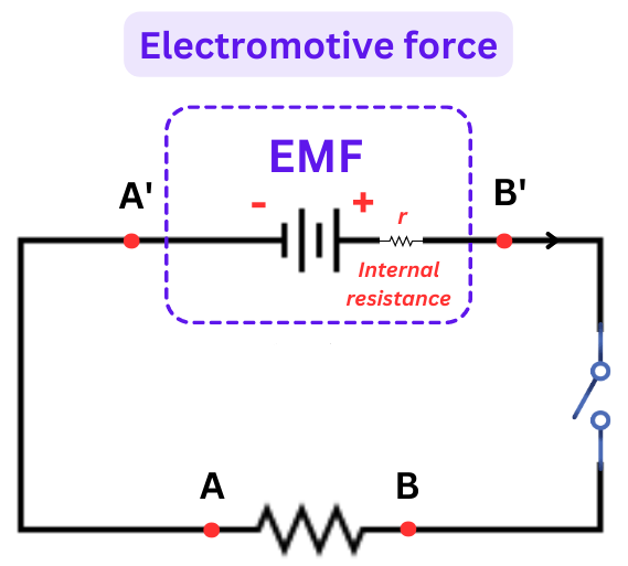
- It represents the energy supplied by a cell, battery, or generator per coulomb of charge.
- It is a measure of how much energy the source provides to each coulomb of charge to drive current through the circuit.
\(\text{e.m.f.} = \dfrac{\text{Electrical Work Done (W)}}{\text{Charge (Q)}}\)
- The unit of e.m.f. is volt (V), where \( 1 \, \text{V} = 1 \, \text{J/C} \)
- The symbol for electromotive force is usually \( \mathcal{E} \) or simply \( \text{e.m.f.} \)
Example:
A battery supplies 12 J of energy to move 4 C of charge around a circuit. What is the electromotive force of the battery?
▶️ Answer/Explanation
Using the formula: \( \text{e.m.f.} = \dfrac{W}{Q} \)
\( \text{e.m.f.} = \dfrac{12 \, \text{J}}{4 \, \text{C}} = 3 \, \text{V} \)
Answer: \(\boxed{3 \, \text{V}}\)
Example:
If a cell has an e.m.f. of 1.5 V, how much energy does it give to 10 C of charge?
▶️ Answer/Explanation
Using the formula: \( W = \text{e.m.f.} \times Q \)
\( W = 1.5 \, \text{V} \times 10 \, \text{C} = 15 \, \text{J} \)
Answer: \(\boxed{15 \, \text{J}}\)
Potential Difference (p.d.):
Potential difference (p.d.) between two points in a circuit is defined as the work done by a unit charge in moving through a component or part of the circuit.
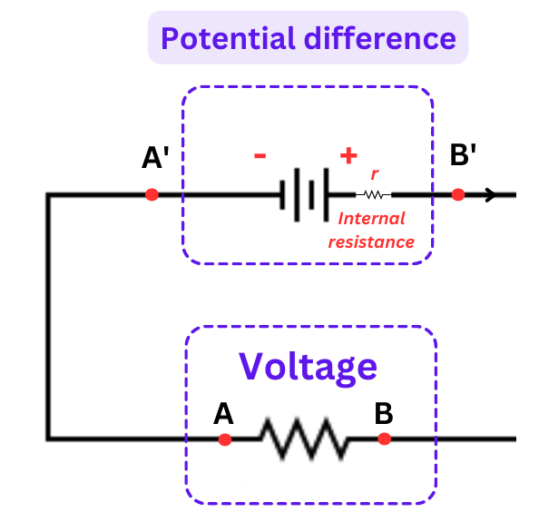
- It represents the amount of energy converted from electrical energy to other forms (like heat, light, motion) per coulomb of charge.
\(\text{p.d.} = \dfrac{\text{Work Done (W)}}{\text{Charge (Q)}}\)
- The unit of potential difference is volt (V), where \( 1 \, \text{V} = 1 \, \text{J/C} \).
- It is measured using a voltmeter, which must be connected in parallel with the component.
Example
If 10 J of energy is used to move 2 C of charge through a resistor, what is the potential difference across it?
▶️ Answer/Explanation
Using: \( \text{p.d.} = \dfrac{W}{Q} \)
\( \text{p.d.} = \dfrac{10 \, \text{J}}{2 \, \text{C}} = 5 \, \text{V} \)
Answer: \(\boxed{5 \, \text{V}}\)
Example
A 6 V battery is connected to a bulb. If 3 C of charge passes through the bulb, how much energy is converted by the bulb?
▶️ Answer/Explanation
Using: \( W = \text{p.d.} \times Q \)
\( W = 6 \, \text{V} \times 3 \, \text{C} = 18 \, \text{J} \)
Answer: \(\boxed{18 \, \text{J}}\)
Voltmeters (Analogue and Digital):
A voltmeter is an instrument used to measure the potential difference (voltage) between two points in an electric circuit.
- Voltmeters can be either analogue or digital.
1. Analogue Voltmeter:

- Uses a moving needle over a calibrated scale to indicate voltage.
- May have a dial or multiple scales for different voltage ranges (e.g., 0–5 V, 0–10 V, 0–50 V).
- Less precise than digital voltmeters but useful for showing trends or changes over time.
2. Digital Voltmeter:

- Displays voltage as a number on a digital screen (LCD/LED).
- More accurate and easier to read than analogue meters.
- Often auto-ranging: they automatically select the best scale for the input voltage.
3. Voltage Range:
- Voltmeters can have different selectable ranges depending on the expected voltage in the circuit.
- Selecting too low a range may overload the meter, while too high a range may give imprecise readings.
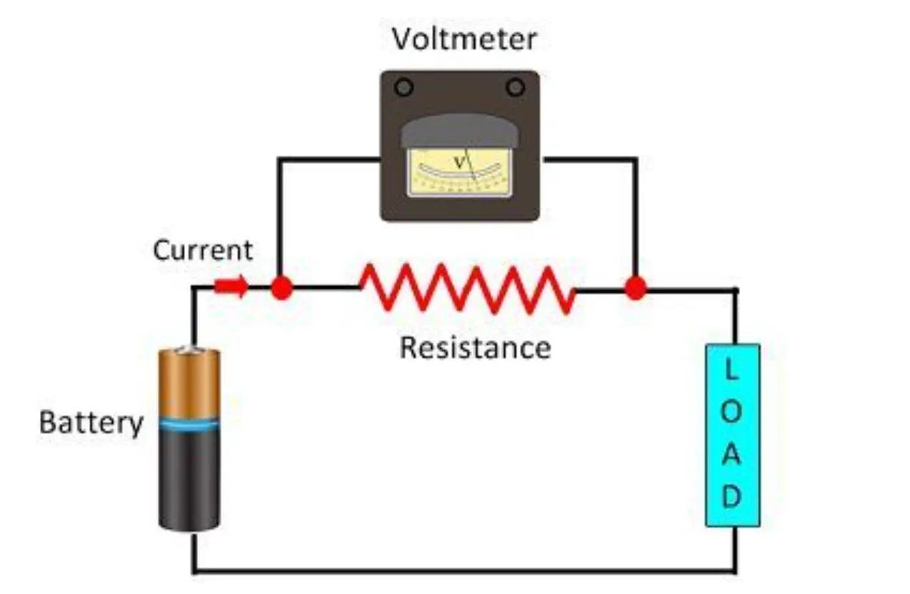
Always connect voltmeters in parallel with the component across which you want to measure voltage.
Example:
A digital voltmeter is used to measure the voltage across a resistor in a circuit. The expected voltage is around 4.5 V. What voltage range should be selected if the meter has settings of 0–5 V, 0–10 V, and 0–50 V?
▶️ Answer/Explanation
Since the expected voltage is 4.5 V, the 0–5 V range is suitable and will give the most precise reading.
Answer: \(\boxed{0\text{–}5 \, \text{V range}}\)