Question
The graph shows how current I varies with potential difference V across a component X.
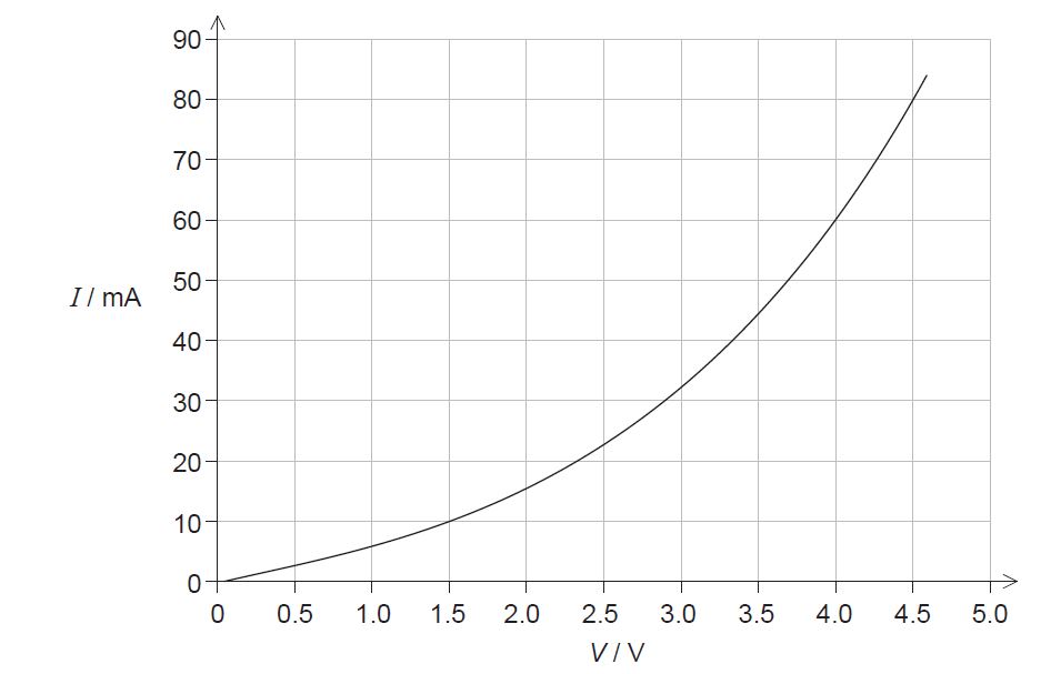
- Outline why component X is considered non-ohmic. [1]
Component X and a cell of negligible internal resistance are placed in a circuit. A variable resistor R is connected in series with component X. The ammeter reads 20 mA. [3]
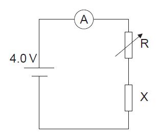
b. Determine the resistance of the variable resistor.[3]
c. Calculate the power dissipated in the circuit.[1]
Component X and the cell are now placed in a potential divider circuit.
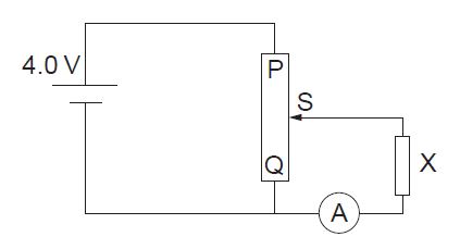
d. State the range of current that the ammeter can measure as the slider S of the potential divider is moved from Q to P.[1]
e. Describe, by reference to your answer for (c)(i), the advantage of the potential divider arrangement over the arrangement in (b).[2]
▶️Answer/Explanation
Ans:
a. current is not «directly» proportional to the potential difference
OR
resistance of X is not constant
OR
resistance of X changes «with current/voltage»
b. ALTERNATIVE 1
voltage across X = 2.3 «V» ✓
voltage across R«= 4.0 − 2.3» =1.7 «V» ✓
resistance of variable resistor 1.7/0.020= 85 Ω
ALTERNATIVE 2
overall resistance 4.0/0.020 = 200 Ω
resistance of X 2.3/0.020 = 115 Ω
resistance of variable resistor «= 200 −115» = 85 Ω
c. power «= 4.0×0.020» = 0.080 «W»
d. from 0 to 60 mA
e. allows zero current through component X / potential divider arrangement ✓
provides greater range «of current through component X»
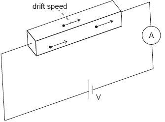
An ohmic conductor is connected to an ideal ammeter and to a power supply of output voltage V.
The following data are available for the conductor:
density of free electrons = 8.5 × 1022 cm−3
resistivity ρ = 1.7 × 10⁻⁸ Ωm
dimensions w × h × l = 0.020 cm × 0.020 cm × 10 cm.
The ammeter reading is 2.0 A.
a. Calculate the resistance of the conductor.[2]
▶️Answer/Explanation
Markscheme
a.
1.7 × 10⁻⁸ × \(\frac{{0.10}}{{{{(0.02 \times {{10}^{ – 2}})}^2}}}\)
0.043 «Ω»[2 marks]
v «= \(\frac{I}{{neA}}\)» = \(\frac{2}{{8.5 \times {{10}^{22}} \times 1.60 \times {{10}^{ – 19}} \times {{0.02}^2}}}\)
0.368 «cms–1»
0.37 «cms–1»
Award [2 max] if answer is not expressed to 2 sf.[3 marks]
The diagram shows a potential divider circuit used to measure the emf E of a cell X. Both cells have negligible internal resistance.
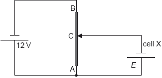
AB is a wire of uniform cross-section and length 1.0 m. The resistance of wire AB is 80 Ω. When the length of AC is 0.35 m the current in cell X is zero.
a. State what is meant by the emf of a cell.[2]
▶️Answer/Explanation
Markscheme
a.
the work done per unit charge
in moving charge from one terminal of a cell to the other / all the way round the circuit
Award [1] for “energy per unit charge provided by the cell”/“power per unit current”
Award [1] for “potential difference across the terminals of the cell when no current is flowing”
Do not accept “potential difference across terminals of cell”[2 marks]
the resistance is proportional to length / see 0.35 AND 1«.00»
so it equals 0.35 × 80
«= 28 Ω»[2 marks]
current leaving 12 V cell is \(\frac{{12}}{{80}}\) = 0.15 «A»
OR
E = \(\frac{{12}}{{80}}\) × 28
E = «0.15 × 28 =» 4.2 «V»
Award [2] for a bald correct answer
Allow a 1sf answer of 4 if it comes from a calculation.
Do not allow a bald answer of 4 «V»
Allow ECF from incorrect current[2 marks]