Essential Idea:
Capacitors can be used to store electrical energy for later use.
Understandings:
- Capacitance
- Dielectric materials
- Capacitors in series and parallel
- Resistor-capacitor (RC) series circuits
- Time constant
Applications and Skills:
- Describing the effect of different dielectric materials on capacitance
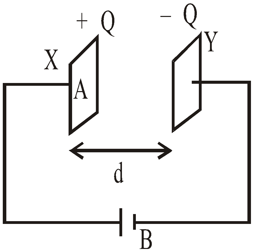
- Solving problems involving parallel-plate capacitors
- Investigating combinations of capacitors in series or parallel circuits
- Determining the energy stored in a charged capacitor
- Describing the nature of the exponential discharge of a capacitor
- Solving problems involving the discharge of a capacitor through a fixed resistor
- Solving problems involving the time constant of an RC circuit for charge, voltage and current
Data booklet reference:
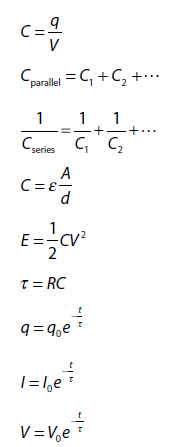
CAPACITORS AND CAPACITANCE
ENERGY STORED IN A CAPACITOR
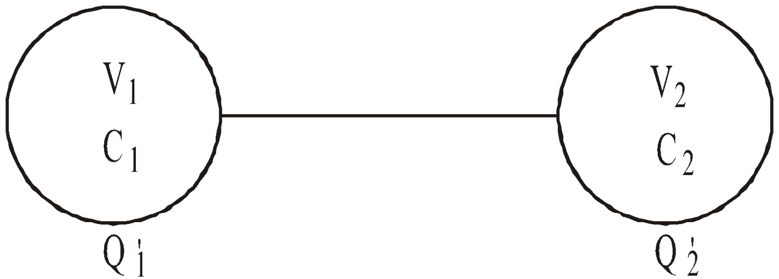
SHARING OF CHARGES

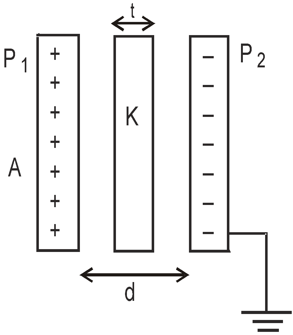
PARALLEL PLATE CAPACITOR
EFFECT OF DIELECTRIC ON CAPACITANCE
 ,
,
- The unit farad is quite a big unit for practical purposes. Even the capacitance of a huge body like earth is 711 μF.
- A capacitor is a device which stores charges and produces electricity whenever required.
- If the two plates of a capacitor is connected with a conducting wire, sparking takes place which shows that electrical energy is converted into heat and light energy.
- A capacitor allows A.C. but doesn’t allow D.C. to pass through it.
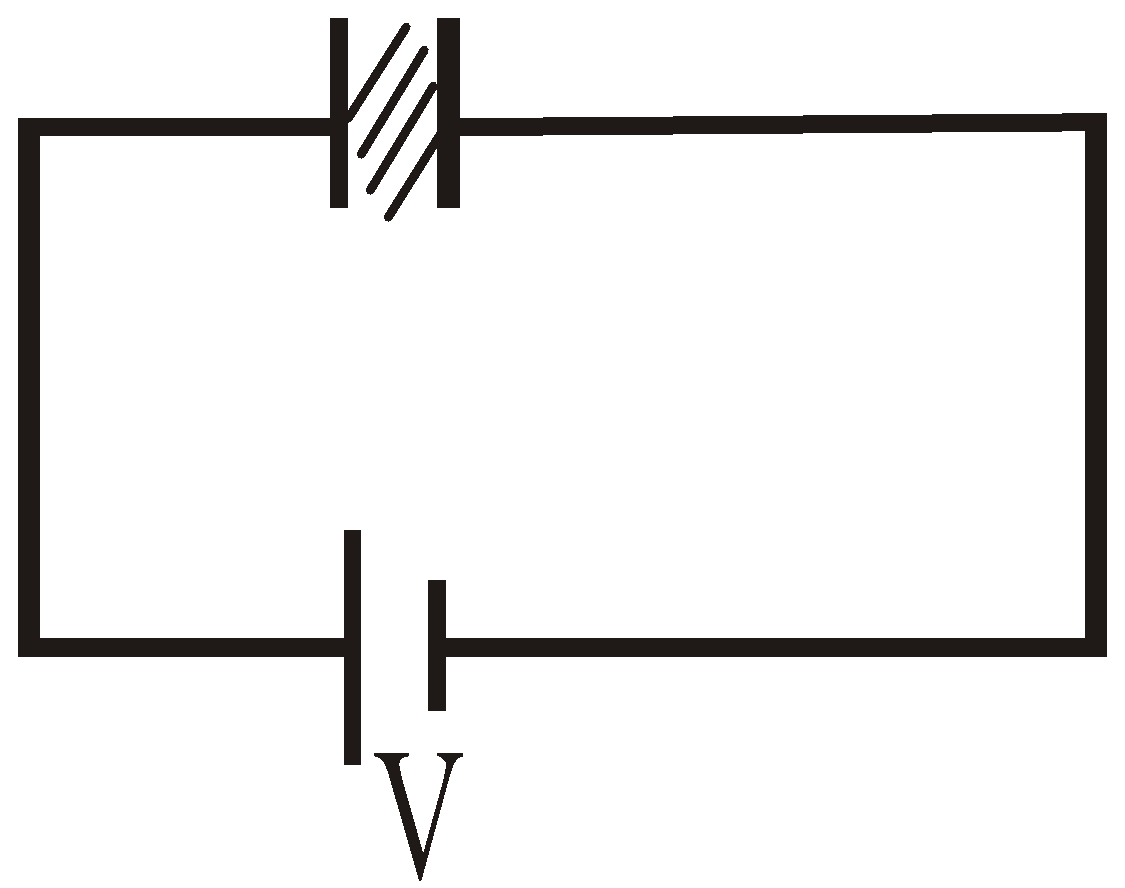
- The capacitance of a capacitor increases with insertion of a dielectric between its plates and decreases with increase in the separation between the plates.
- The capacitance of a capacitor increases K times if a medium of dielectric constant K is inserted between its plates.
- The energy of a capacitor for a particular separation between the plates is the amount of work done in separating the two plates to that separation if they are made to touch to each other.
- The loss of energy when the two charged conductors are connected by a wire doesn’t depend on the length of the wire.
SPHERICAL CAPACITOR
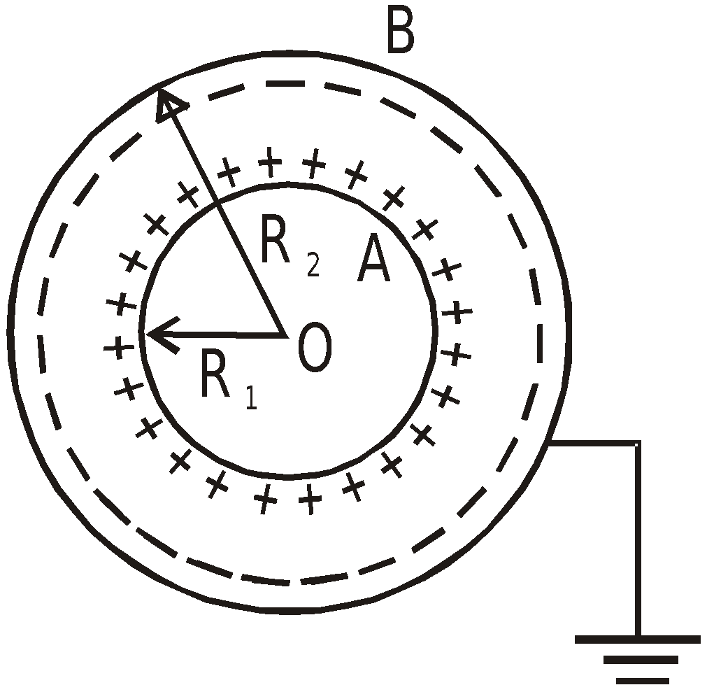
- When outer conductor is earthed,
- When inner sphere is earthed,
CYLINDRICAL CAPACITOR
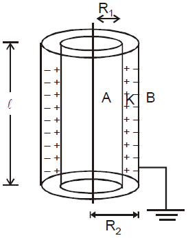
 (without dielectric)
 (with dielectric)
COMBINATION OF CAPACITORS
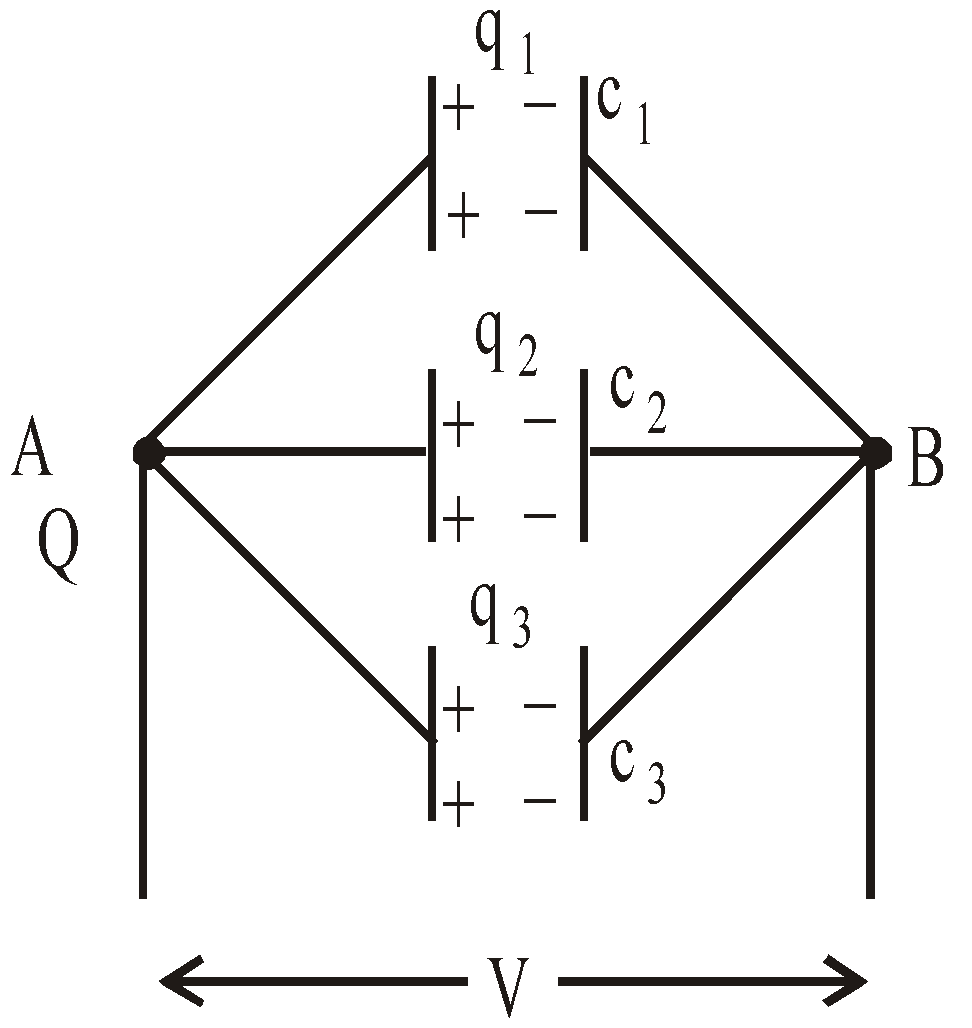
SERIES COMBINATION
- In this combination, the positive plate of one capacitor is connected to the negative plate of the other.
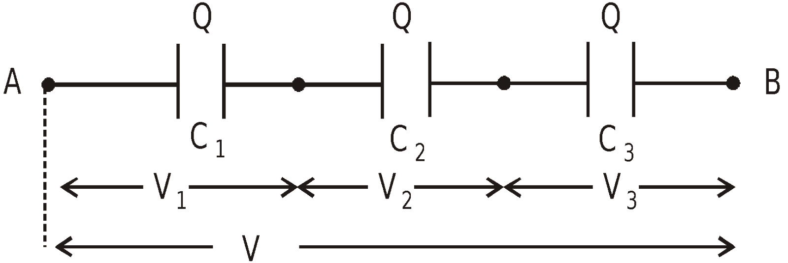
- The charges of individual capacitor are equal.
- The potential difference is shared by the capacitors in the inverse ratio of their capacities
- The equivalent capacitance (C) between A and B is
PARALLEL COMBINATION
- In this arrangement, +ve plates of all the condensers are connected to one point and negative plates of all the condensers are connected to the other point.
- The Potential difference across the individual capacitor is same.
- The total charge shared by the individual capacitor is in direct ratio of their capacities
- The equivalent capacitance between a and b is ceq = c1 + c2 + c3 + ……..+ cn
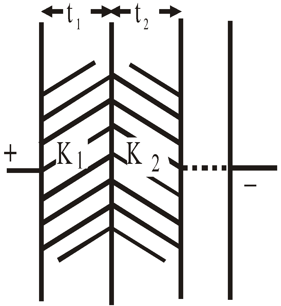
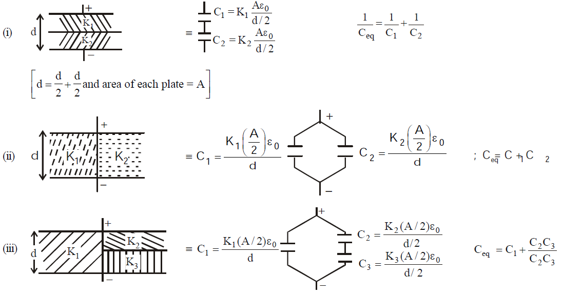
- The capacitance of a parallel plate capacitor having a number of slabs of thickness t1, t2, t3 …. and dielectric constant K1, K2, K3 …. respectively between the plates is

- When a number of dielectric slabs of same thickness (d) and different areas of cross-section A1, A2, A3 … having dielectric constants K1, K2, K3, …. respectively are placed between the plates of a parallel plate capacitor then the capacitance is given by

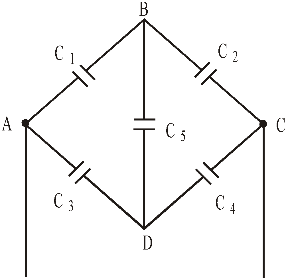
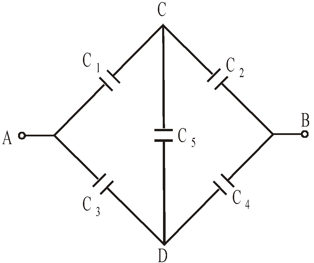
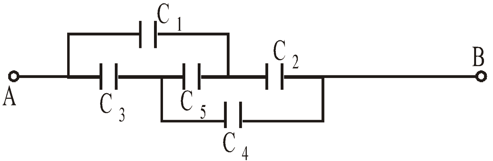
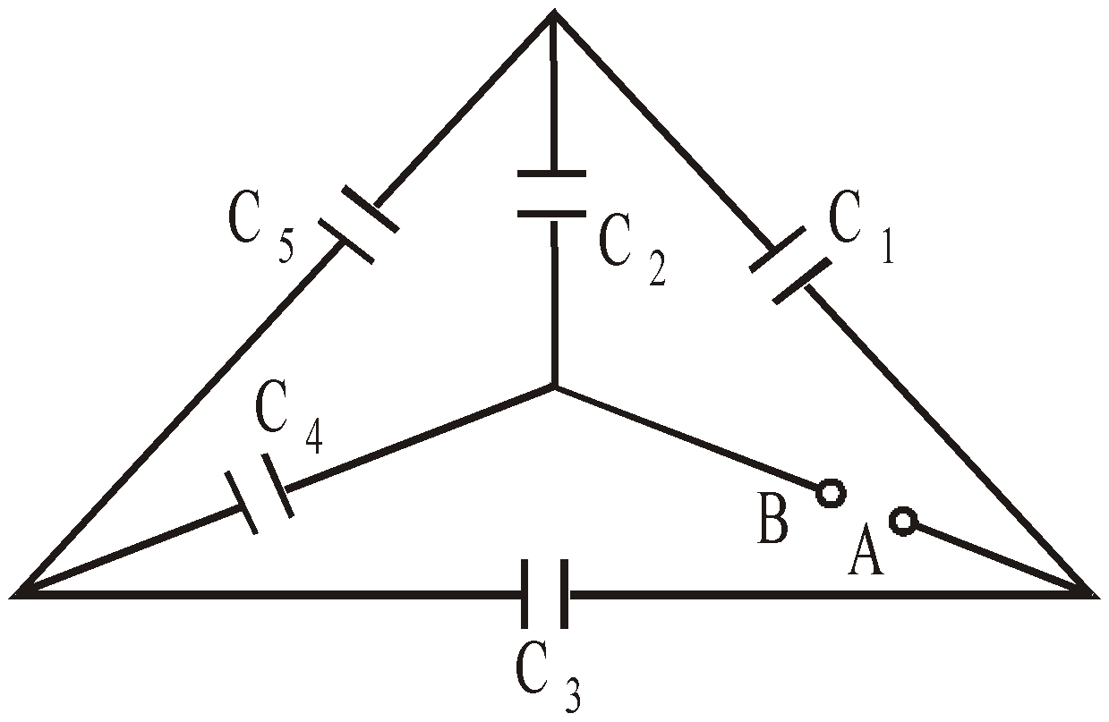
- When five capacitors are connected in wheatstone bridge arrangement as shown, such that
 , the bridge is balanced and C5 becomes ineffective. No charge is stored on C5. Therefore C1, C2 and C3, C4 are in series. The two series combinations are in parallel between A and C. Hence equivalent capacitance can be calculated.
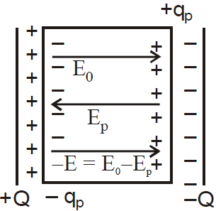
RELATION BETWEEN THREE ELECTRIC VECTORS
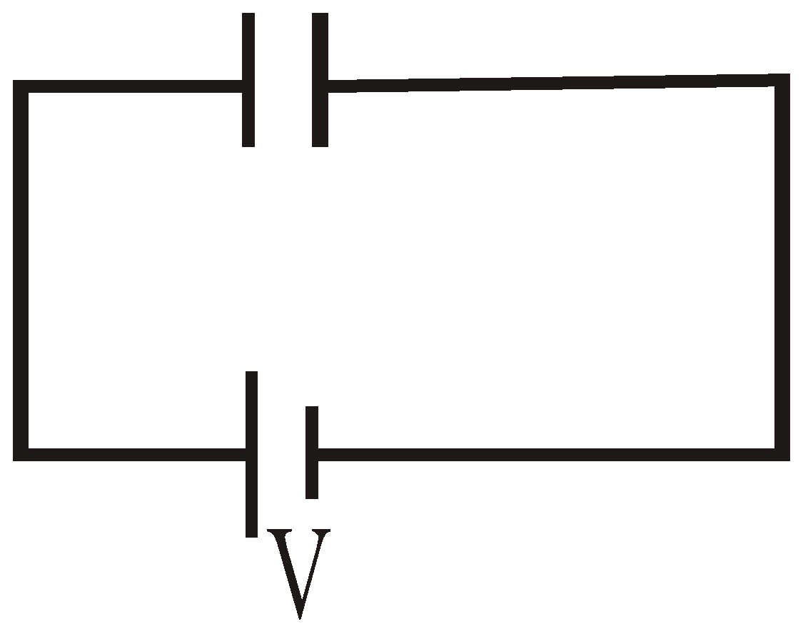
EFFECT OF FILLING DIELECTRIC WITH BATTERY CONNECTED
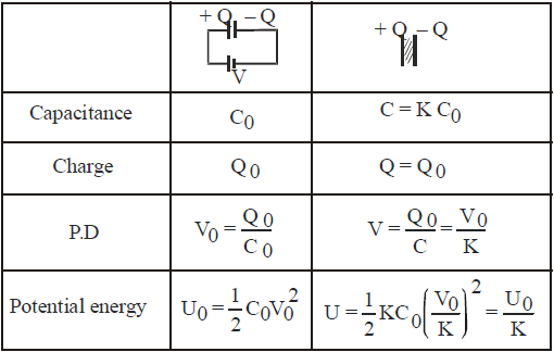
EFFECT OF FILLING A DIELECTRIC IN A CAPACITOR AFTER DISCONNECTION OF BATTERY
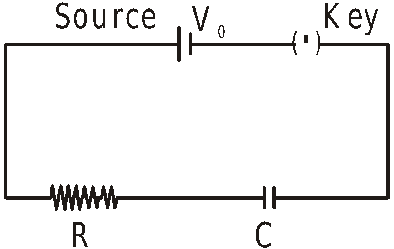
CHARGING AND DISCHARGING A CAPACITOR
CHARGING A CAPACITOR
DURING THE PERIOD OF CHARGING
- The charge on the capacitor increases from ‘zero’ to the final steady charge.
- The potential difference developed across the capacitor opposes the constant potential difference of the source.
- The charge on the capacitor ‘grows’ only as long as the potential difference of source is greater than the potential difference across the capacitor. This transport of the charge from the source to the capacitor constitutes a transient current in the circuit.
- As the charge on the capacitor increases, more energy is stored in the capacitor.
- When the capacitor is fully charged, potential difference across the capacitor is equal to the potential difference of the source and the transient current tends to zero.
i.e.

- At t = 0, q = 0.
- When t increases, q increases.
- As


- At t = CR [‘CR’ has dimensions of time]
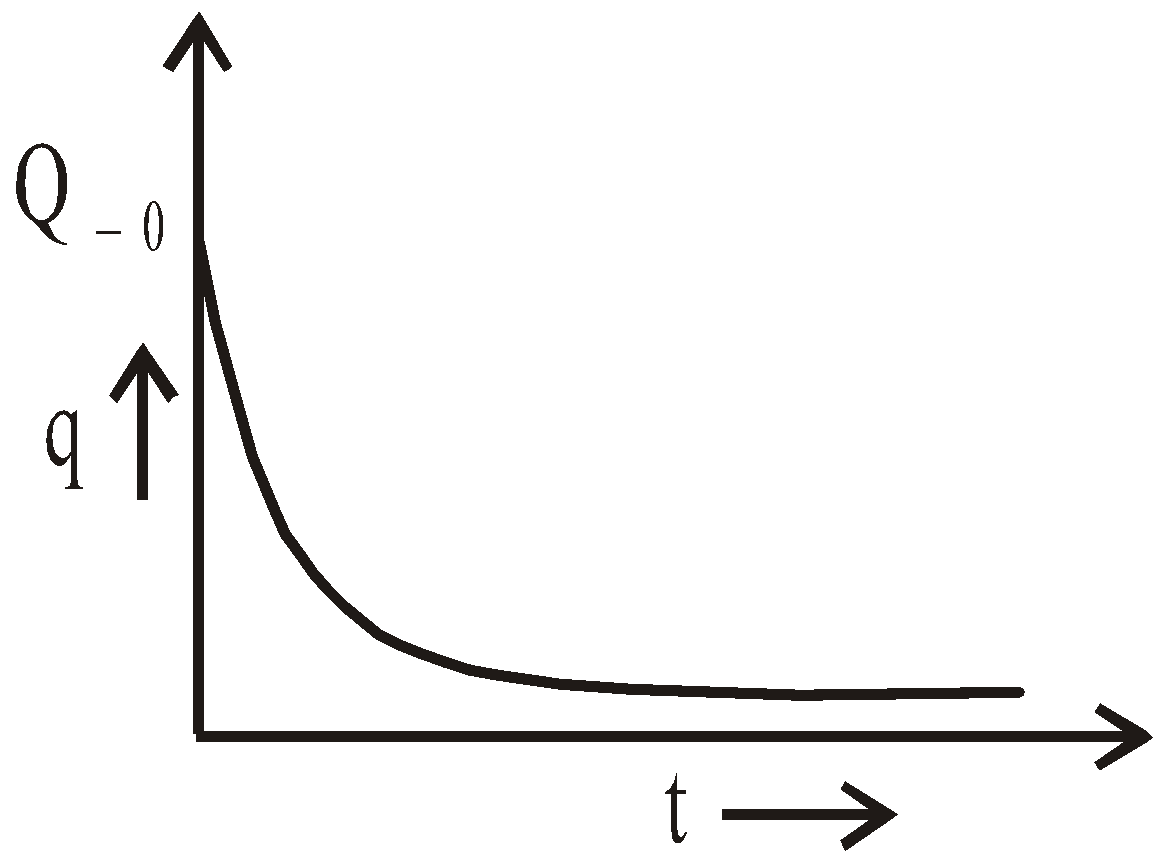
DISCHARGING OF A CAPACITOR
- the initial condition, q = Q0 at t = 0 and
- the final condition, q = 0 at ,

- If n small drops each having a charge q, capacity ‘C’ and potential V coalesce to form a big drop, then
- the charge on the big drop = nq
- capacity of big drop = n1/3 C
- potential of big drop = n2/3 V
- potential energy of big drop = n5/3 U
- surface density of charge on the big drop = n1/3 × surface density of charge on one small drop.
- Charged soap bubble : Four types of pressure act on a charged soap bubble.
- Pressure due to air outside the bubble PO, acting inwards.
- Pressure due to surface tension of soap solution PT, acting inwards.
- Pressure due to air inside the bubble, Pi, acting outwards.
- Electric pressure due to charging, Pe =
 , acting outwards.

- Force of attraction between the plates of a parallel plate capacitor =

- Uses of capacitor :
- In LC oscillators
- As filter circuits
- Tuner circuit in radio etc.
- The total energy stored in an array of capacitors (in series or in parallel) is the sum of the individual energies stored in each capacitor.
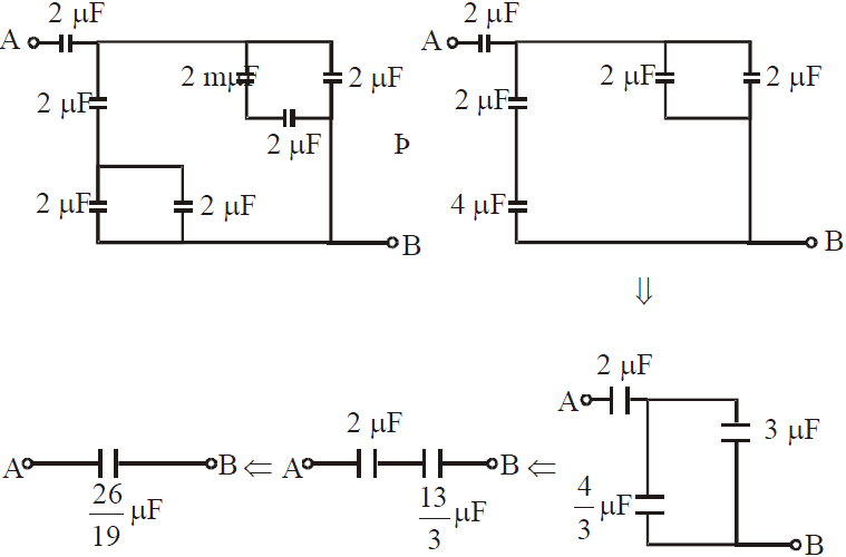
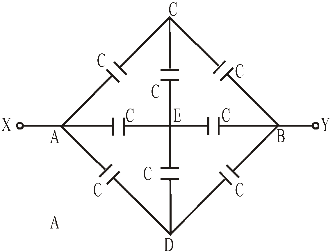
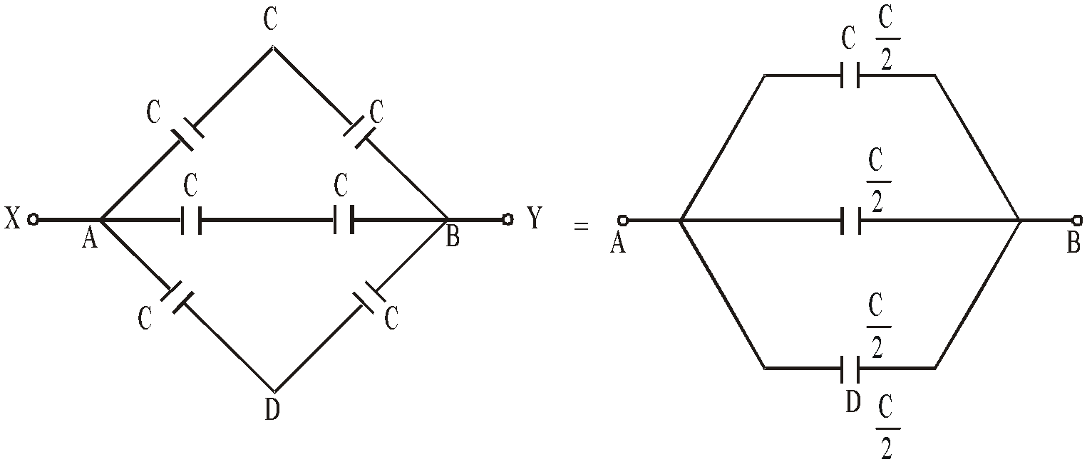
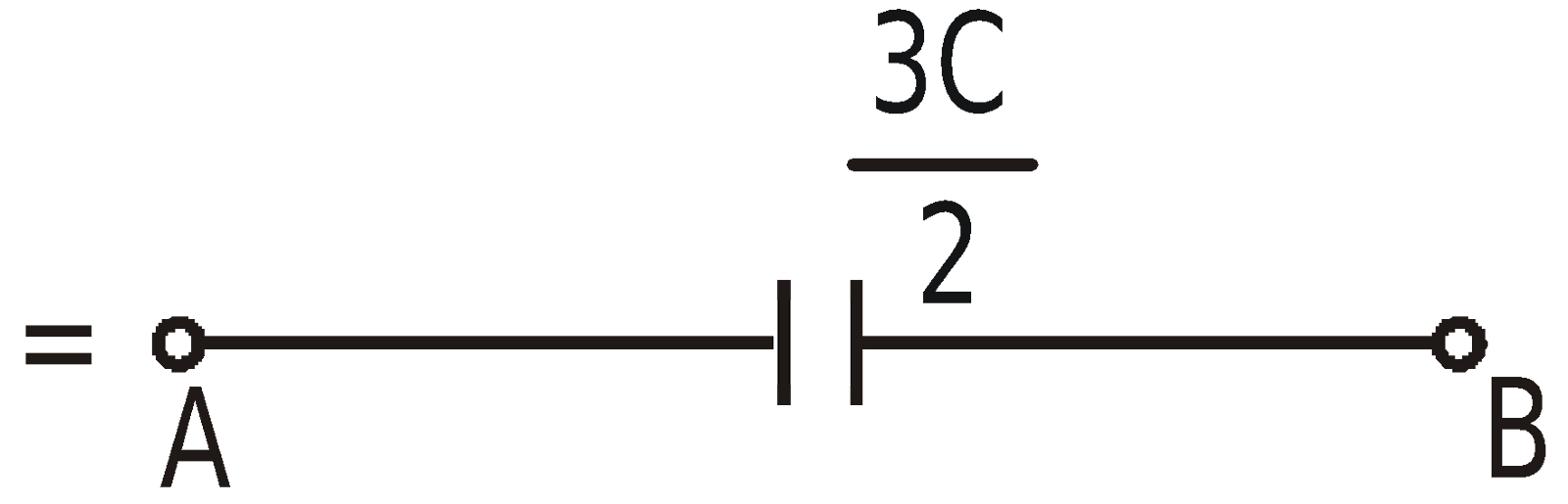
COMBINATION OF CAPACITOR : EQUIVALENT CAPACITANCE
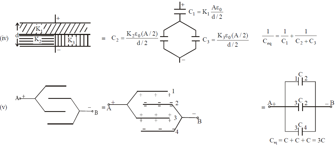
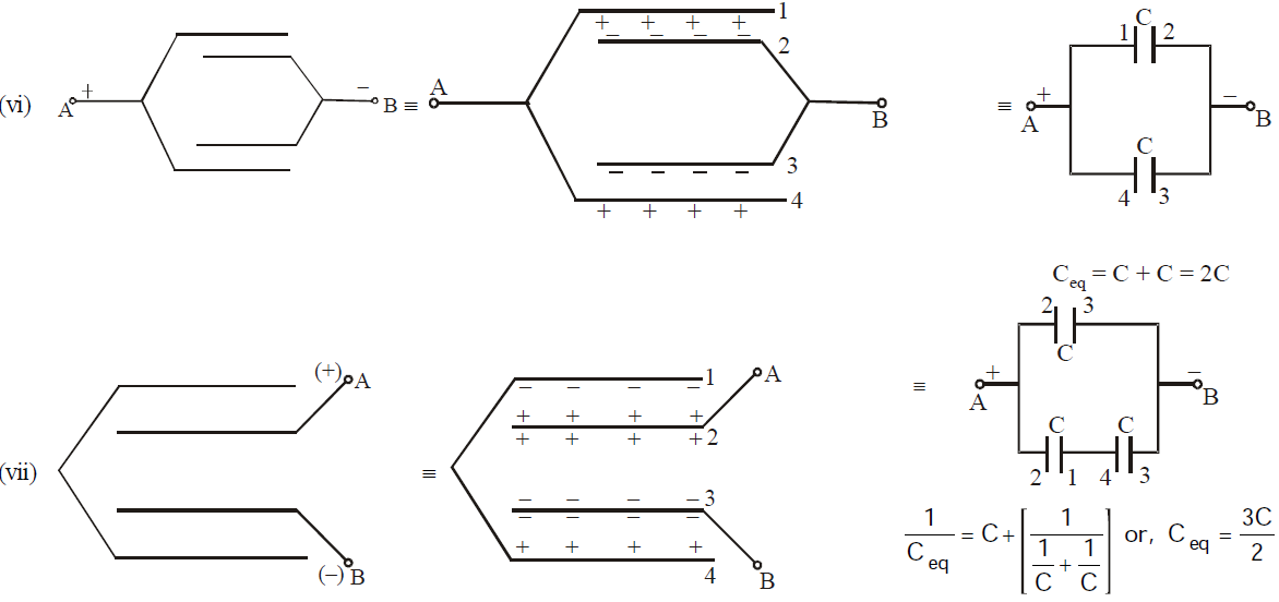
SOME METHODS OF FINDING EQUIVALENT CAPACITANCE
SHARP POINT ACTION (CORONA DISCHARGE)
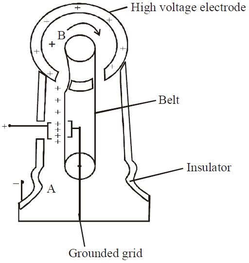
VAN DE GRAAF GENERATOR
Capacitors in rectification
In rectification, to produce a steady direct current or voltage from an alternating current or voltage, a smoothing capacitor is necessary
Smoothing is defined as: The reduction in the variation of the output voltage or current
This works in the following ways:
- A single capacitor with capacitance C is connected in parallel with a load resistor of resistance R
- The capacitor charges up from the input voltage and maintains the voltage at a high level
- As it discharges gradually through the resistor when the rectified voltage drops but the voltage then rises again and the capacitor charges up again
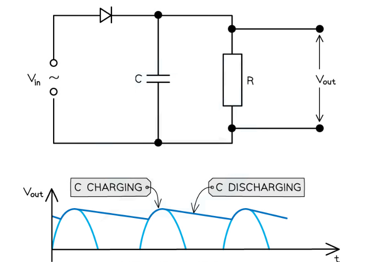
A smoothing capacitor connected in parallel with the load resistor. The capacitor charges as the output voltage increases and discharges as it decreases
- The resulting graph of a smoothed output voltage Vout and output current against time is a ‘ripple’ shape

A smooth, rectified current graph creates a ‘rippling’ shape against time
- The amount of smoothing is controlled by the capacitance C of the capacitor and the resistance R of the load resistor
- The less the rippling effect, the smoother the rectified current and voltage output
- The slower the capacitor discharges, the more the smoothing that occurs ie. smaller ripples
- This can be achieved by using:
- A capacitor with greater capacitance C
- A resistance with larger resistor R
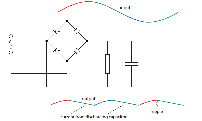
A capacitor in parallel to the load resistor smooths out the output voltage.
For the first half cycle the current is clockwise. The current moves from top to bottom in the load. Now, in the first quarter cycle the capacitor charges. At the end of the first quarter cycle the potential at the top plate of the capacitor is a maximum. In the second quarter cycle (green), the potential at the top plate begins to decrease and so the capacitor discharges, sending current through the load from top to bottom. (The capacitor begins to discharge at the end of the third quarter cycle as well.) The ‘ripple’ is reduced with higher capacitance or load resistance.