▶️ Answer/Explanation
(a)
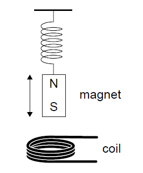
At equilibrium, the weight of the magnet equals the spring force: \(mg = kx\).
\(x = \frac{mg}{k} = \frac{0.12 \times 9.8}{7.4} \approx 0.159\,m\).
Elastic potential energy: \(E_p = \frac{1}{2}kx^2 = \frac{1}{2} \times 7.4 \times (0.159)^2 \approx 9.3 \times 10^{-2}\,J\).
(b)
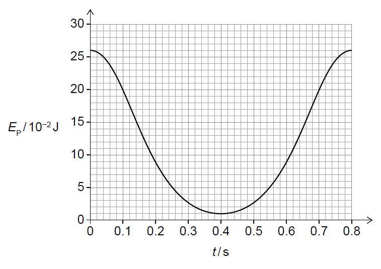
(i) At \(t = 0.2\,s\), the graph shows that the elastic potential energy is decreasing. Since \(E_p \propto x^2\) and the spring is always stretched, the extension is decreasing. Therefore, the magnet is moving upwards towards the equilibrium position.
(ii) Between \(t = 0.2\,s\) and \(t = 0.4\,s\), elastic potential energy is converted into kinetic energy and gravitational potential energy as the magnet rises. The kinetic energy decreases to zero at the upper turning point.
(c)
(i) From the graph, \(E_{p,\max} \approx 0.26\,J\) and \(E_{p,\min} \approx 0.01\,J\).
\(x_{\max} = \sqrt{\frac{2 \times 0.26}{7.4}} \approx 0.265\,m\), \(x_{\min} = \sqrt{\frac{2 \times 0.01}{7.4}} \approx 0.052\,m\).
Amplitude: \(A = \frac{x_{\max} – x_{\min}}{2} \approx 0.106\,m \approx 0.1\,m\).
(ii) Angular frequency: \(\omega = \sqrt{\frac{k}{m}} = \sqrt{\frac{7.4}{0.12}} \approx 7.85\,rad\,s^{-1}\).
Maximum speed: \(v_{\max} = \omega A \approx 7.85 \times 0.106 \approx 0.83\,m\,s^{-1}\).
(iii) From the graph at \(t = 0.15\,s\), \(E_p \approx 0.14\,J\), giving an extension \(x \approx 0.195\,m\). Displacement from equilibrium: \(y = 0.195 – 0.159 = 0.036\,m\).
Oscillatory energy: \(E = \frac{1}{2}kA^2 \approx 4.1 \times 10^{-2}\,J\).
Kinetic energy: \(KE = E – \frac{1}{2}ky^2 \approx 3.6 \times 10^{-2}\,J\).
(d)
(i) An emf is induced due to the changing magnetic flux linkage through the coil (Faraday’s law). Two factors are: speed of oscillation (greater speed increases the rate of change of flux) and number of turns in the coil (emf is proportional to the number of turns).
(ii) When the resistor is connected, an induced current flows in the coil. This produces a magnetic field that opposes the motion of the magnet (Lenz’s law), doing work against the motion. Mechanical energy is dissipated as thermal energy in the resistor, causing the oscillations to be damped and the amplitude to decrease.