Question
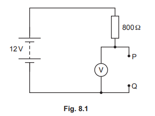
A student sets up a circuit that includes a 12 V battery, an 800 Ω resistor, a voltmeter and a thermistor. Fig. 8.1 is an incomplete circuit diagram because the symbol for the thermistor is missing.
The thermistor is connected between terminals P and Q.
(a) Complete Fig. 8.1 by drawing the symbol for a thermistor between terminals P and Q.
(b) The 12 V battery consists of eight identical cells connected in series.
Calculate the electromotive force (e.m.f.) of each cell.
e.m.f. =
(c) The reading on the voltmeter is 8.0 V.
(i) Determine the resistance of the thermistor.
resistance = ……………………………………………………………..
(ii) A few hours later, the student notices that the reading on the voltmeter is greater.
Explain what can be deduced from this observation.
Answer/Explanation
Answer:
(a)
(b) 1.5 V c.a.o.
(c)(i) 1600 Ω
(\(V_{800 Ω}\) =) 4.0 (V)
(I =) V / R in any form or 4.0 / 800 or 0.0050 (A) or ( R =) V / I or 8.0 / 0.0050
OR
1600 Ω
\((V_{800 Ω}\) =) 4.0 (V)
(\(R_{Th}\) =) \(R_{800 Ω}\) × \(V_{Th}\) / \(V_{800 Ω}\) in any form or (\(R_{Th}\) =) 800 × 8.0 / 4.0 in any form
OR
1600Ω ![]()
![]()
(c)(ii) larger proportion of the e.m.f. (across thermistor) or smaller voltage across 800Ω
temperature (of thermistor) is smaller / has decreased
resistance of thermistor / circuit is large(r)
Question
(a) Define electromotive force (e.m.f.).
(b)Fig. 8.1 shows a source E of e.m.f. 60 V in a circuit.
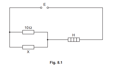
The heater H has a resistance of 22.5 Ω and the potential difference (p.d.) across it is 45 V. Calculate:
(i) the power of the heater
power = …………………………………………….
(ii) the p.d. across resistor X
p.d. = ……………………………………
(ii) the current in the 10 Ω resistor.
current = ……………………………………
Answer/Explanation
Answer:
(a)energy supplied by a source in driving charge around a complete circuit / energy needed to drive unit charge / 1 coulomb
round circuit
(b)(i) ( P=) 90 W
(P=) V I in any form
(V / R OR I =) 2
(b)(ii) (p.d. =) 15 V
(p.d. =) 60 –45
(b)(iii) (I = 15 / 10 =) 1.5 A
(I =) V / R OR V = I R in any form
Question
The power supply used in an electric vehicle contains 990 rechargeable cells each of electromotive force (e.m.f.) 1.2 V.
The cells are contained in packs in which all the cells are in series with each other. The e.m.f. of each pack is 54 V.
(a) Calculate the number of packs in the power supply.
number of packs
(b) When in use, each pack supplies a current of 3.5 A.
(i) Calculate the rate at which each cell is transferring chemical energy to electrical energy.
rate of energy transfer =
(ii) The packs are connected in parallel to supply a large current to drive the electric vehicle.
Explain why it is necessary to use thick wires to carry this current.
Answer/Explanation
Answer:
(a) 990 / (54 / 1.2) OR 990 / 45 OR (number of cells in pack =) 54 / 1.2 OR 45
22
(b) (i) (P =) EI OR 1.2 × 3.5
4.2 W OR 4.2 J / s
(b) (ii) thick wires have a smaller resistance
less thermal energy generated in wires
more efficient OR less risk of fire / insulation melting
Question
Fig. 7.1 shows a circuit including a 12V battery and two identical lamps.
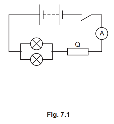
(a) The 12V battery consists of cells connected in series. Each cell in the battery has an electromotive force (e.m.f.) of 1.5V.
Determine how many cells are in the battery.
number of cells = [1]
(b) (i) When the switch is closed, the ammeter reading is 2.4A.
Calculate the total resistance of the circuit.
resistance = [2]
(ii) Each lamp has a resistance of 3.0Ω.
Calculate the resistance of Q.
resistance of Q = [2]
(c) (i) On Fig. 7.1, draw the symbol for a voltmeter that measures the potential difference (p.d.) across the two lamps. [1]
(ii) Calculate the power supplied to one lamp.
power = [3] [Total: 9]
Answer/Explanation
Ans:
(a) 8 (cells)
(b)(i) (12 / 2.4 =) 5.0 Ω
R = V / I in any form
(b)(ii) (Resistance of Q = 5–1.5) = 3.5 Ω
1 / R = 1 / R1 + 1 / R2 OR R= R1R2 / (R1+R2)
(c)(i) correct voltmeter symbol connected correctly across both lamps B1
(c)(ii) 4.3 W
(P = ) IV in any form OR 1.2 × 3.6
3.6 V OR 1.2 A
Question
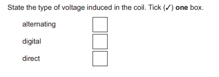
A student uses a coil and a magnet on a spring to generate an electromotive force (e.m.f.) that varies. He suspends the magnet above a coil as shown in Fig. 11.1.
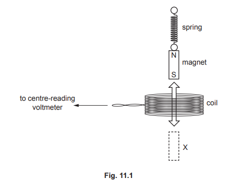
(a) The student pulls the magnet through the coil to X and then releases it. The magnet moves up and down through the coil.
 [1]
[1]
(b) State two ways of increasing the voltage induced in the coil.
1. ……………………………………………………………………………………………………………………………..
2. ……………………………………………………………………………………………………………………………..[2] [Total: 3]
Answer/Explanation
Ans: (a)top box ticked (alternating)
(b) any two from:increase strength of magnet/magnetic field
increase speed of magnet increase number of turns (of wire in coil)
