Question:
Combinations of logic gates are used when digital signals are processed.
(a) Describe the difference between a digital signal and an analogue signal. You may include a diagram if it helps your answer.
Answer/Explanation
Ans: digital (signal) consists of 1(s) and 0(s) / high value and low
analogue (signal) is (continuously) variable (in magnitude)
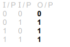
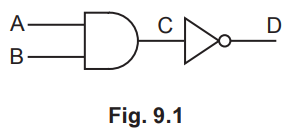
(b) Fig. 9.1 is the truth table for a logic gate X.
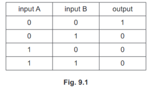
State the name of logic gate X and draw the symbol that represents it.
name ………………………………………………………………………………………………………………………..
symbol
Answer/Explanation
Ans: NOR (gate) ![]()
(c) Logic gate Y is identical to logic gate X.
Draw a combination of logic gates X and Y that behaves like an OR gate. Label the inputs A and B and label the output Q.
Answer/Explanation
Ans: 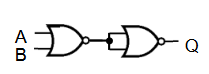
![]() (i.e. NOR gate symbol with two inputs joined seen)
(i.e. NOR gate symbol with two inputs joined seen)
Question
(a) Write down the truth table for an OR gate.
(b) Draw the symbol for a NOR gate.
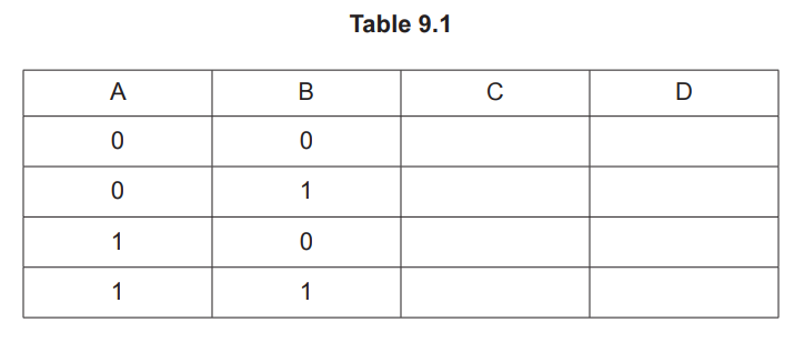
(c) Fig. 9.1 shows a digital circuit designed to produce the values shown in Table 9.1 for the
output S from the two inputs P and Q.
(i) Table 9.1 is the truth table for the circuit shown in Fig. 9.1.
Table 9.1
P | Q | R | S |
0 | 0 |
| 0 |
0 | 1 |
| 0 |
1 | 0 |
| 1 |
1 | 1 |
| 0 |
Complete the column for point R in Table 9.1.
(ii) State which type of gate is used for gate X. Explain your answer.
statement …………………………………………………………………………………………………………..
explanation ……………………………………
Answer/Explanation
Answer:
(a)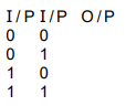
(b) two inputs to curved face, sharp end with small circle and one output
c(i)![]()
(c)(ii) AND
input 1 and 1 gives output 1
any 0 input gives 0 output
Question
(a) Describe how a digital signal differs from an analogue signal. You may draw a diagram.
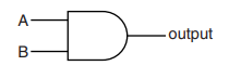
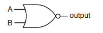
(b) (i) In the appropriate box, draw the symbol for an AND gate and the symbol for an OR gate.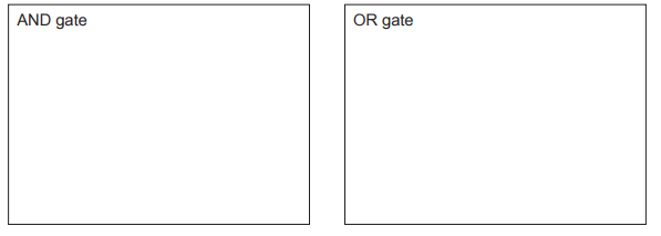
(ii) State how the behaviour of an AND gate differs from that of an OR gate.
(c) An arrangement of logic gates A, B and C is shown in Fig. 9.1. The arrangement has two
inputs, X and Y and two outputs P and Q.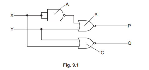
(i) Determine the logic states of the two inputs of logic gate B.
upper input =
lower input =
(ii) Determine and explain the logic state of output Q.
logic state of Q =
Answer/Explanation
Answer:
(a) digital signal: consists of high and low states / voltages
analogue signal: continuously varying voltage
(b) (i) 
(b) (ii) when the inputs differ AND ‘AND gate’ produces 0 AND ‘OR gate’ produces 1
(c) (i) both inputs to upper NOR gate are 0s
(c) (ii) two (identical) inputs to NAND gate are 1s
lower input to lower NOR gate is 1
output Q is 0
Question
(a) State the name of the logic gate with the symbol shown in Fig. 9.1.
![]()
Fig. 9.1
……………………………………………………………………………………………………………………………
(b) State the name of the logic gate with the truth table shown in Table 9.1.
Table 9.1
input | output |
0 | 1 |
1 | 0 |
……………………………………………………………………………………………………………………………
(c) Fig. 9.2 shows a digital circuit.
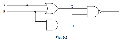
Complete the truth table in Table 9.2 for this circuit for all possible combinations of input.
Table 9.2
A | B | C | D | E |
1 | 1 | |||
1 | 0 | |||
1 | 0 | |||
0 | 0 |
Answer/Explanation
Answer:
(a) NAND
(b) NOT
(c) AB 1st row 11 AND 4th row 00
AB 2nd and 3rd row 01 AND 10 in any order
E 1st two rows 0 1
E last two rows 1 1
Question
(a) (i) Fig. 11.1 shows the symbol for a logic gate and its truth table.
input A | input B | output |
0 | 0 | 0 |
1 | 0 | 0 |
0 | 1 | 0 |
1 | 1 | 1 |
Fig. 11.1
State the name of this logic gate …………………………………………………………………….
(ii) Complete the truth table for the logic gate shown in Fig. 11.2.
input A | input B | output |
0 | 0 |
|
1 | 0 |
|
0 | 1 |
|
1 | 1 |
|
Fig. 11.2
(b) Fig. 11.3 shows the system of logic gates used to ensure the security of the strongroom of a bank. 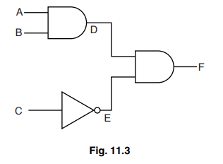
The strongroom door will only open when the output F is logic 1.
Complete the table to show the logic states at A, B, C, D and E when the strongroom door can be opened.
input A | input B | input C | output D | output E | output F |
|
|
|
|
| 1 |
Answer/Explanation
Answer:
(a) AND (gate)
(b)
0 0 1
1 0 0
0 1 0
1 1 0
(c) 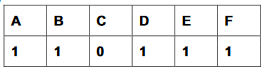
Question
(a)(i)Fig. 10.1 shows the symbol for a circuit component.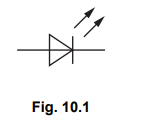
Name this component.
(ii) In the space below, draw the symbol for a NOT gate.
(b) Fig. 10.2 shows a digital circuit. 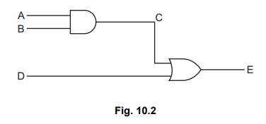
Complete the truth table for this circuit.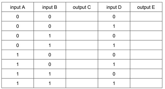
(c) Suggest a modification to the circuit in Fig. 10.2 to produce the output Z in the truth table below.
It may help you to compare this truth table with the truth table in (b).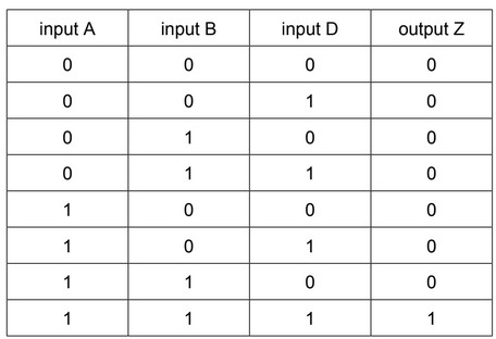
Answer/Explanation
Answer:
(a)(i) Light emitting diode OR LED
(a)(ii)![]()
(b)
(c) Replace the OR gate with an AND gate
Question
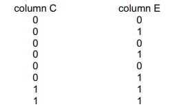
Fig. 9.1 shows a digital circuit.
(a) (i) Explain what is meant by digital.[1]
(ii) Table 9.1 is a truth table for the digital circuit shown in Fig. 9.1.
Complete the columns C and D in Table 9.1.[2]
(b) State the single logic gate that would produce the same output D from inputs A and B.[1] [Total: 4]
Answer/Explanation
Ans:
(a)(i) (A signal that has one of) two possible states B1
(a)(ii)
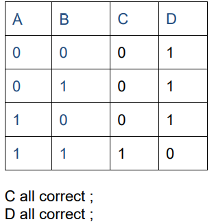
(b) NAND