ELECTROSTATIC POTENTIAL AND CAPACITANCE
ELECTROSTATIC POTENTIAL
Electric potential at a point in an electric field is defined as the amount of work done in bringing a unit positive test charge from infinity to that point along any arbitrary path. (Infinity is taken as point of zero potential). It is denoted by V ;

Its SI unit is JC–1 or volt. It is a scalar quantity.
Also, electric potential at any point in an electric field is defined as the negative line integral of the electric field vector from a point infinitely away from all charges to that point
i.e. 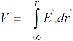

POTENTIAL DUE TO A POINT CHARGE
The electric potential due to a point charge q at separation r is given by
(Please note that we have to write q with its sign in this formula)
4F potential difference between two points is the work done in bringing unit positive charge from one point to another.
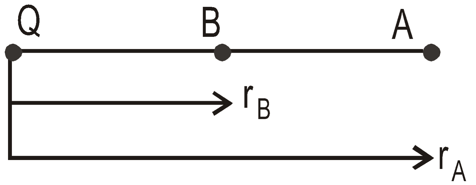
VAB = VB – VA 
 J/C
J/C
POTENTIAL DUE TO CONTINUOUS CHARGE DISTRIBUTION
The potential due to a continuous charge distribution is the sum of potentials of all the infinitesimal charge elements in which the distribution may be divided.
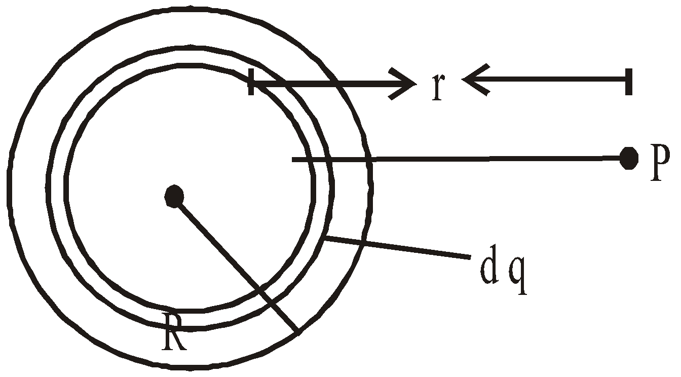
i.e.  where
where 
POTENTIAL DUE TO A SYSTEM OF CHARGES
The electric potential due to a system of charges q1, q2, …qn is
V = V1 + V2 + … + Vn
V = V1 + V2 + … + Vn
where ri is the point from charge qi and ε is the permittivity of medium in which the charges are situated.
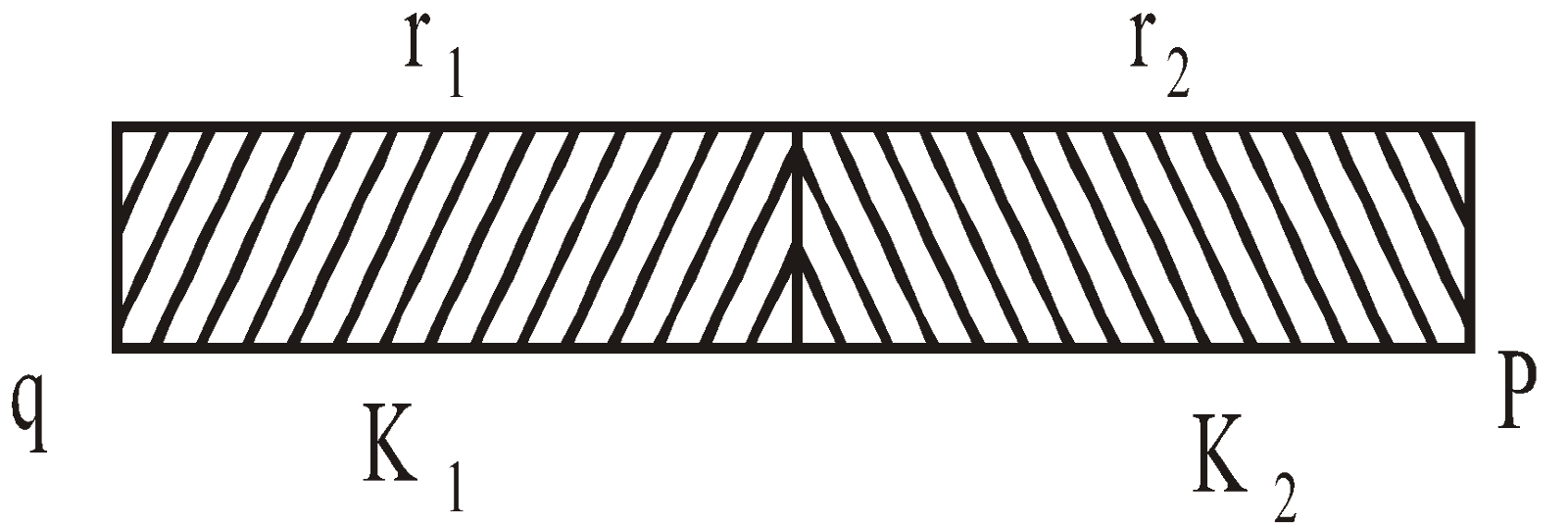
Potential at any point P due to a point charge q at a distance (r1 + r2) where r1 is the thickness of medium of dielectric constant x1 and r2 is the thickness of the medium of dielectric constant k2
RELATION BETWEEN ELECTRIC FIELD AND POTENTIAL
The relation between electric field (E) and potential (V) is 
For 3-D we can write
So electric field is equal to negative potential gradient.
In this relation negative sign indicates that in the direction of electric field, potential decreases. Consider two points A and B situated in a uniform electric field at a distance d then,
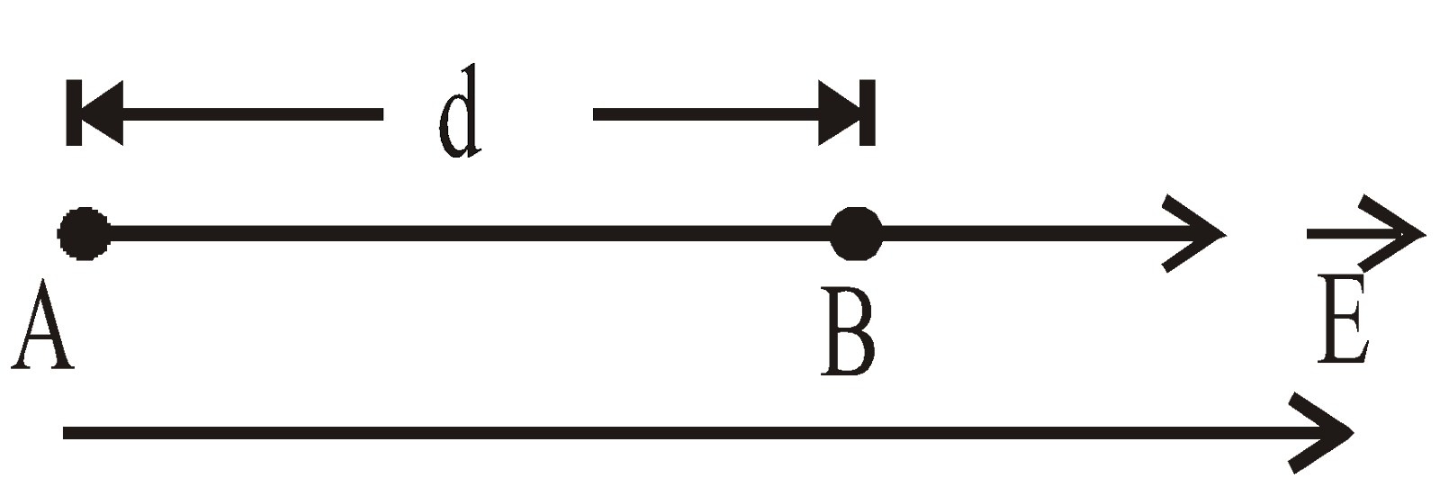
The potential difference between A and B is
CONSERVATIVE NATURE OF ELECTRIC FIELD
The electric field is conservative in nature. In figure the work, WAB has the same value whatever path is taken in moving the test charge.
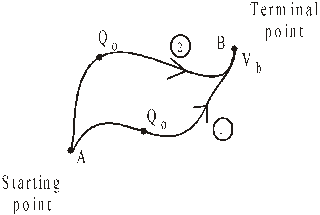
so, 
has the same value for any path between A and B and VB and VA are unique for the points A and B.
Note:- We cannot find the absolute value of potential therefore conventionally, we take infinity as the point of zero potential. If need arises, we can assume any point to be the point of zero potential and find the potential of other points on this basis.
POTENTIAL ENERGY OF A SYSTEM OF CHARGES
Potential energy can be defined only for those forces, which are conservative, such as gravitational and electrostatic forces. The potential energy of a charge between two points is defined as the amount of work done in bringing the charge from one point to another.
i.e. 
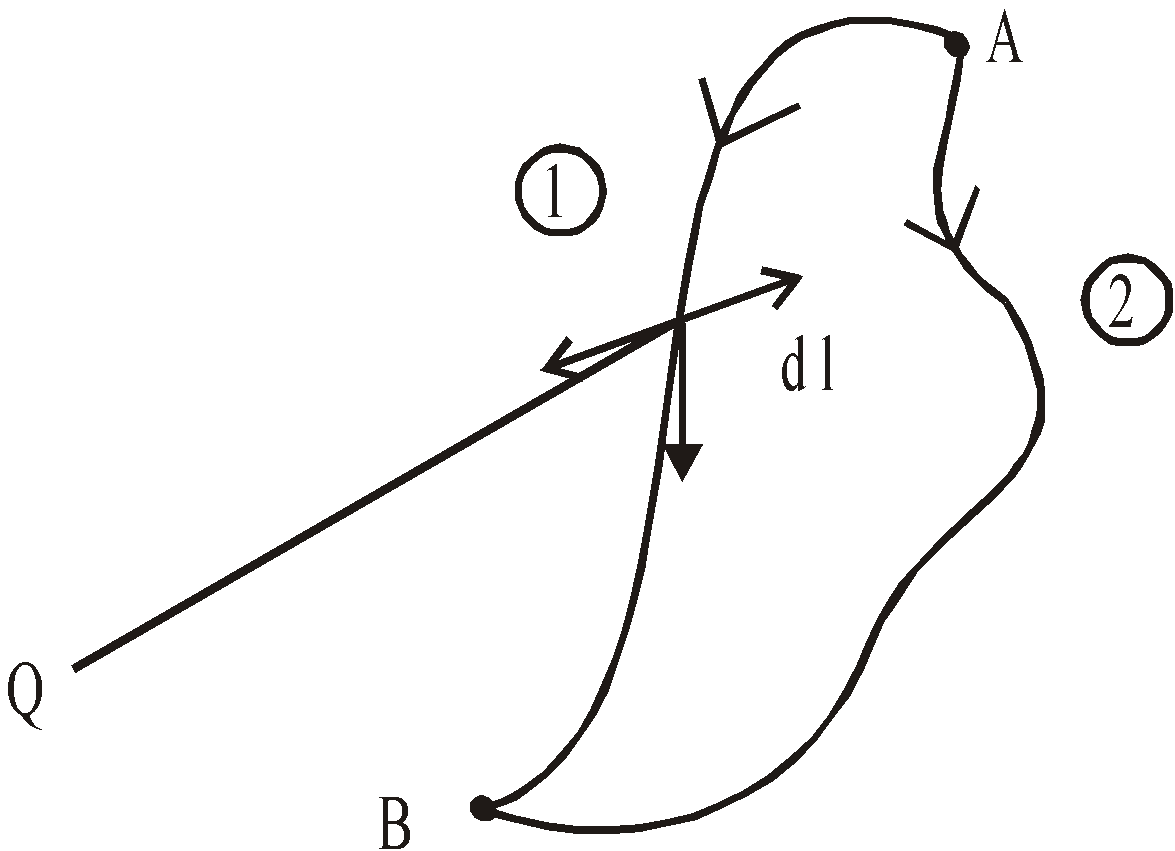
Calculation of external work done against the field and a point charge Q in moving a test charge q from A to B. For a conservative field the work done by any path is same. The sectional force is – qE.
If A is at infinity then at infinity since potential is zero we assume infinity as reference point,VA = 0

Potential energy of a system of two charges Q1 and Q2

Note:- In this formula we have to write charges with sign
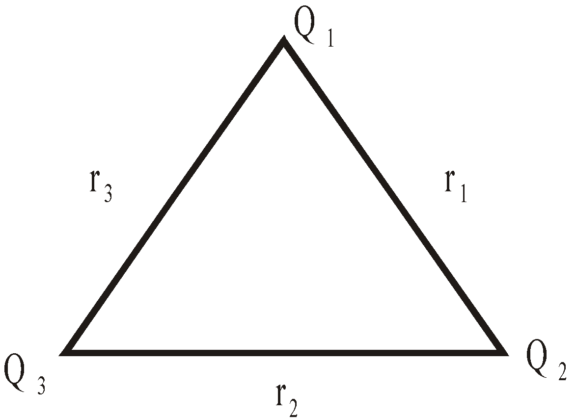
Potential energy of a system of three charges Q1, Q2 and Q3

KEEP IN MEMORY
- For an assembly of n charges
[Total number of intersection ] the potential energy is

- For a system of two charges.
If Usystem = –ve, then there is net force of attraction between the charges of the system.
If Usystem = +ve, then there is net force of repulsion between the charges of the system
Usystem = max for unstable equilibrium
Usystem = min for stable equilibrium
Also 
- The energy required to take away the charges of a dipole at infinite distance

- The work done when a charge q is moved across a potential difference of V volt is given by W = qV
- When one electronic charge (1.6×10⁻¹⁹ coulomb i.e., charge of electron) is moved across one volt the work done is called one electron volt (eV). Thus 1eV = (1 volt) × (1.6×10⁻¹⁹ coulomb) = 1.6×10⁻¹⁹ joule.
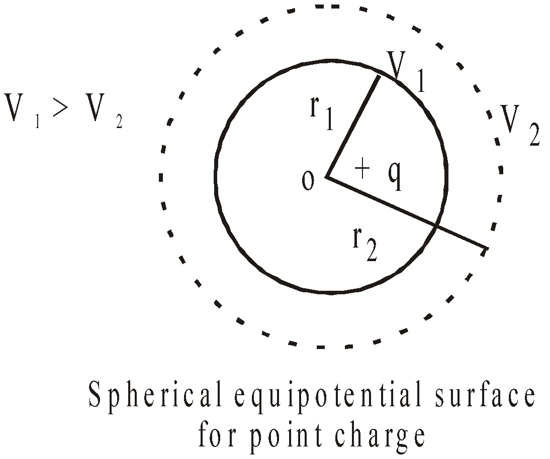
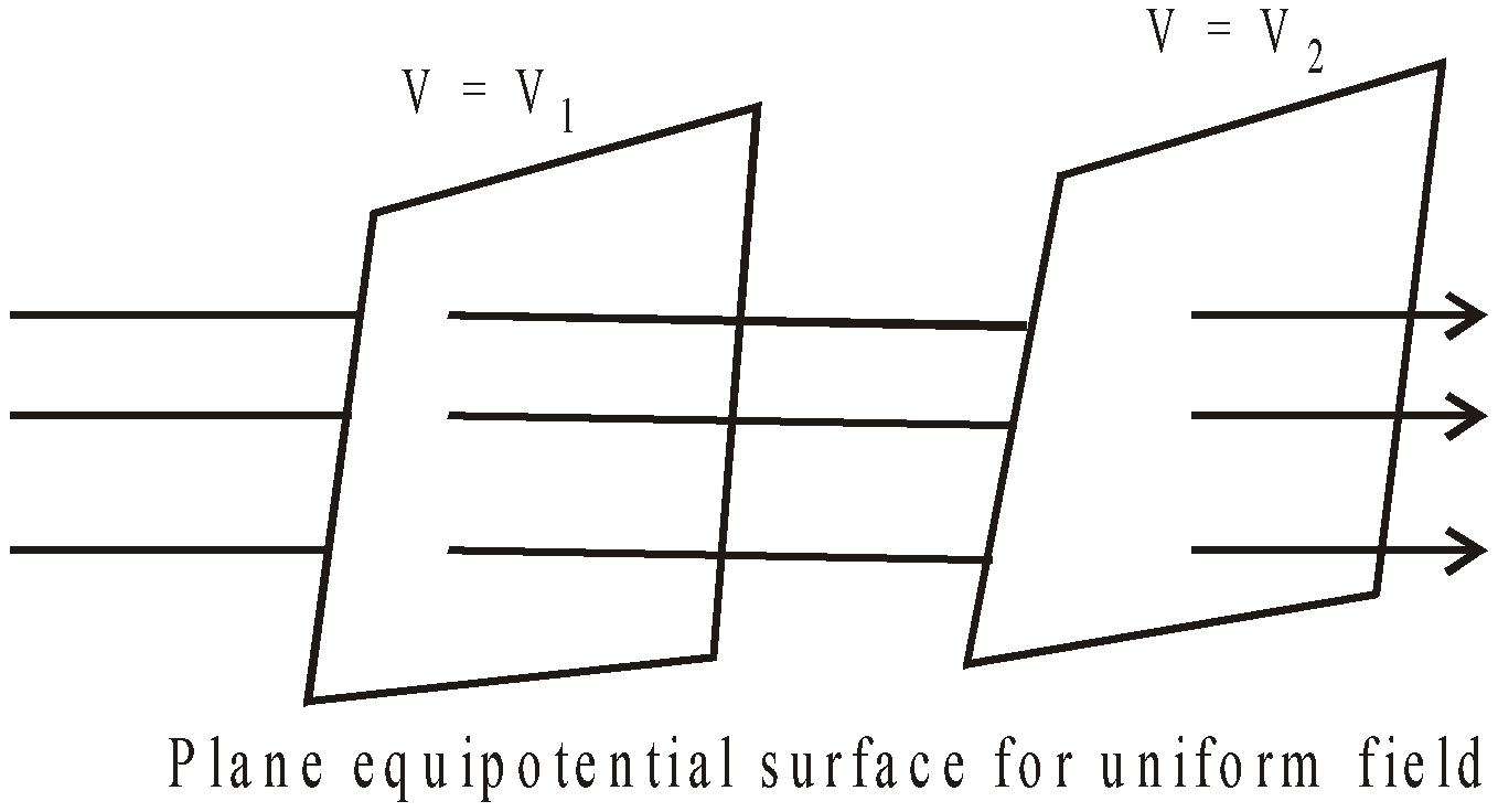
EQUIPOTENTIAL SURFACE
It is that surface where the potential at any point of the surface has the same value. The electric lines of force and the equipotential surface are mutually perpendicular to each other. No work is done in moving a charge from one point to other on an equipotential surface. Work is done in moving a charge from one equipotential surface to another.
Equipotential surface do not cut each other.
The density of the equipotential lines gives an idea of the strength of electric field at that point. Higher the density, larger is the field strength.
POTENTIAL DUE TO VARIOUS CHARGE DISTRIBUTION
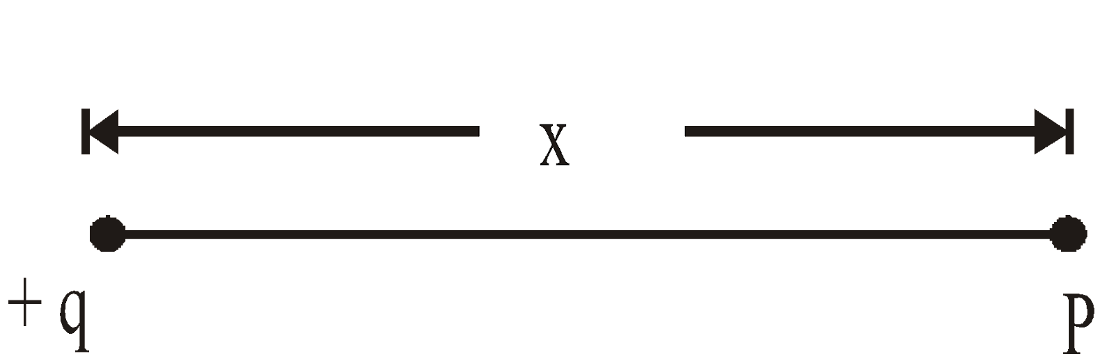
- Electric potential due to isolated point charge
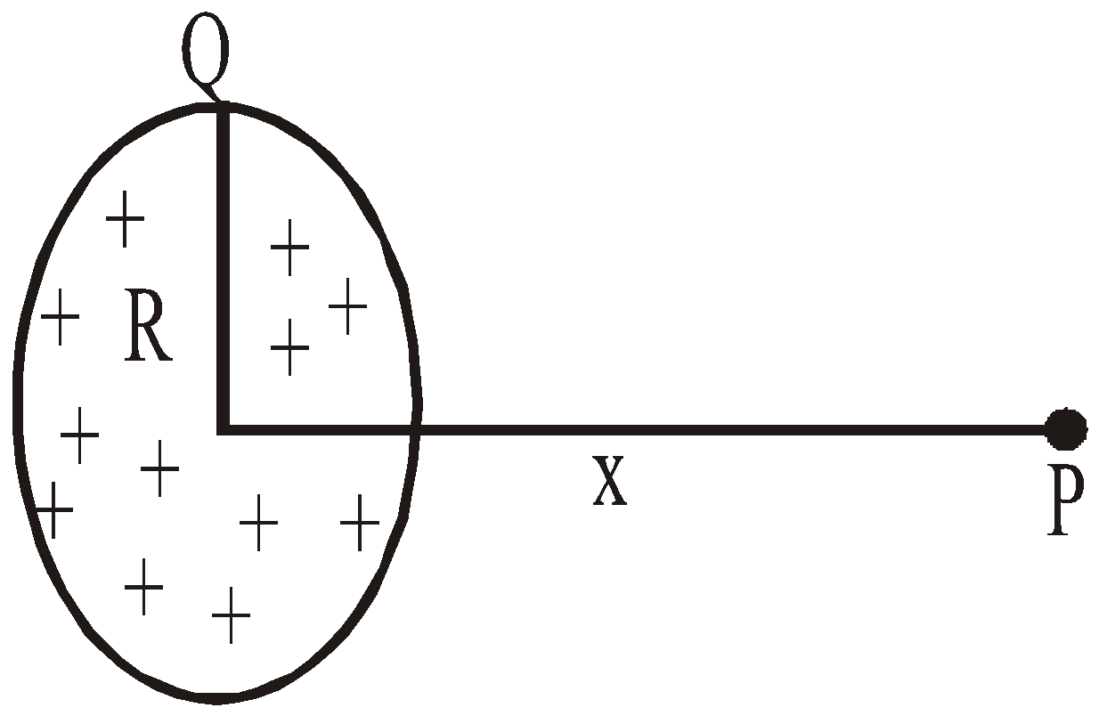
- A circular ring of radius R with uniformly distributed charge Q
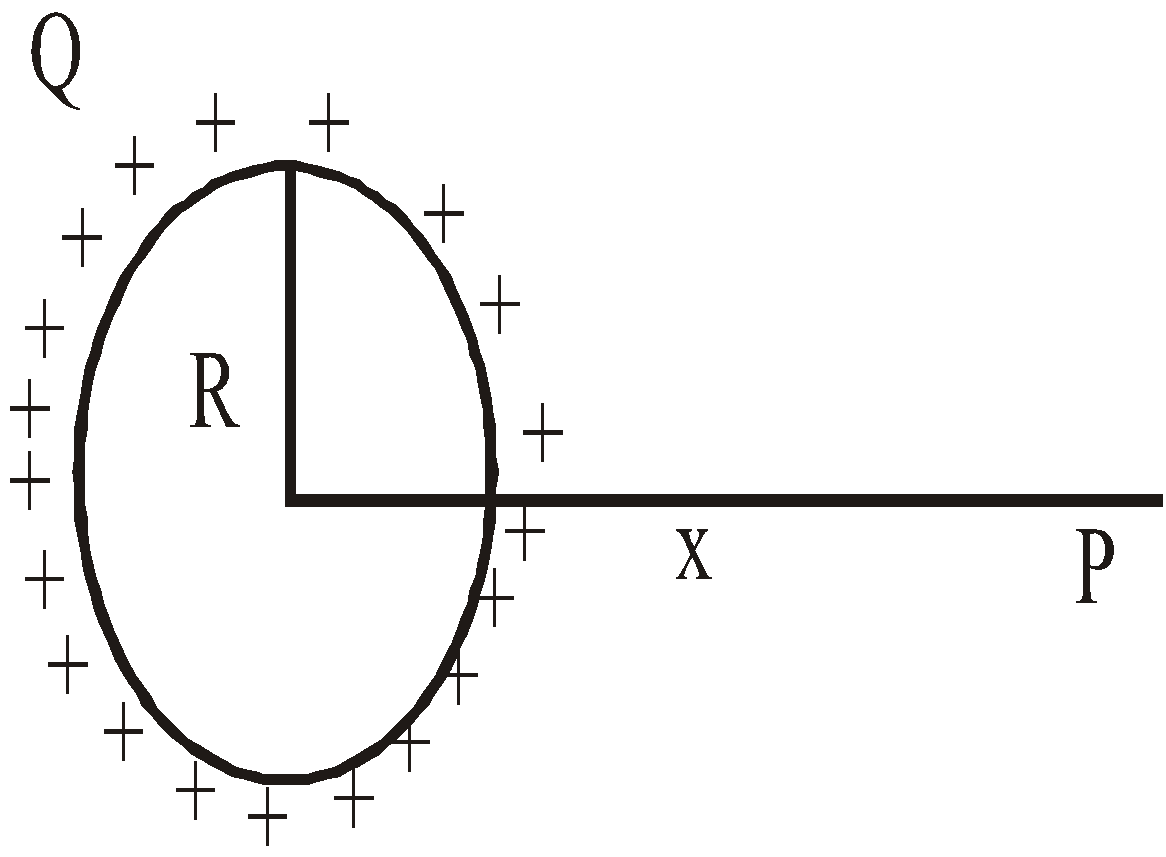
Potential V does not depend on the way of charge distribution on the ring (uniform / non-uniform).
- A circular disc of radius R with uniformly distributed charge with surface charge density σ
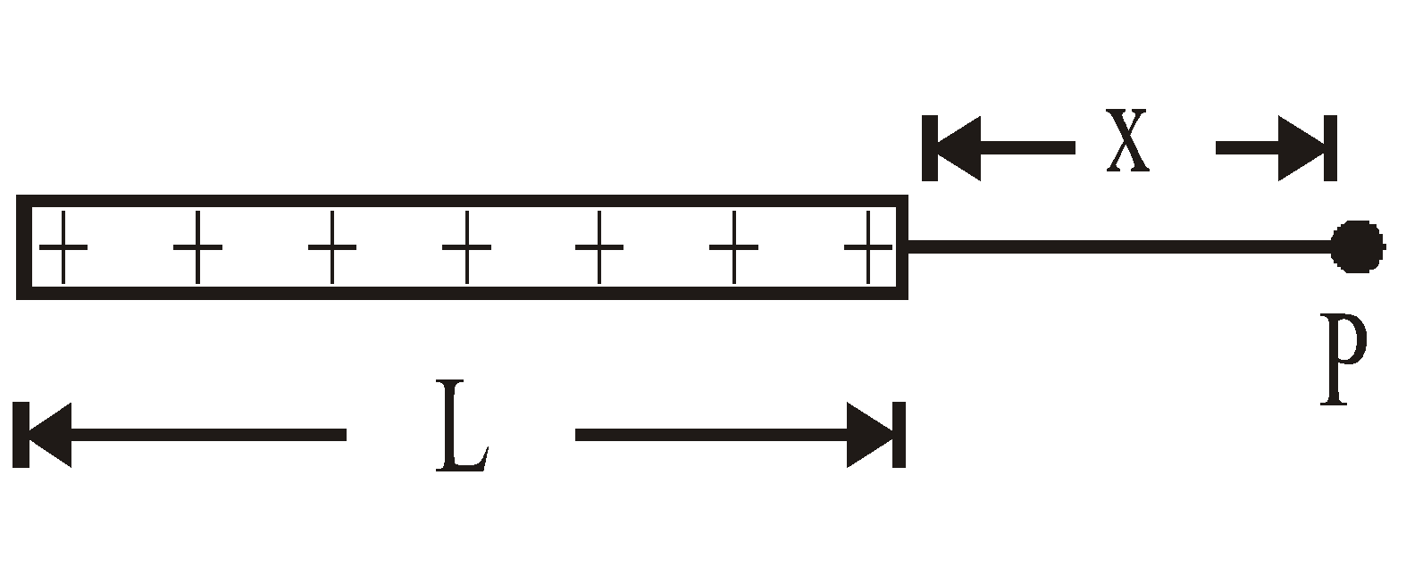
- A finite length of charge with linear charge density
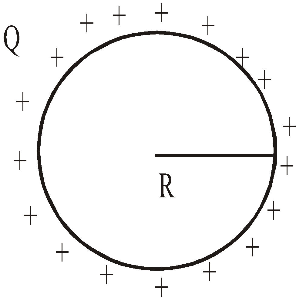
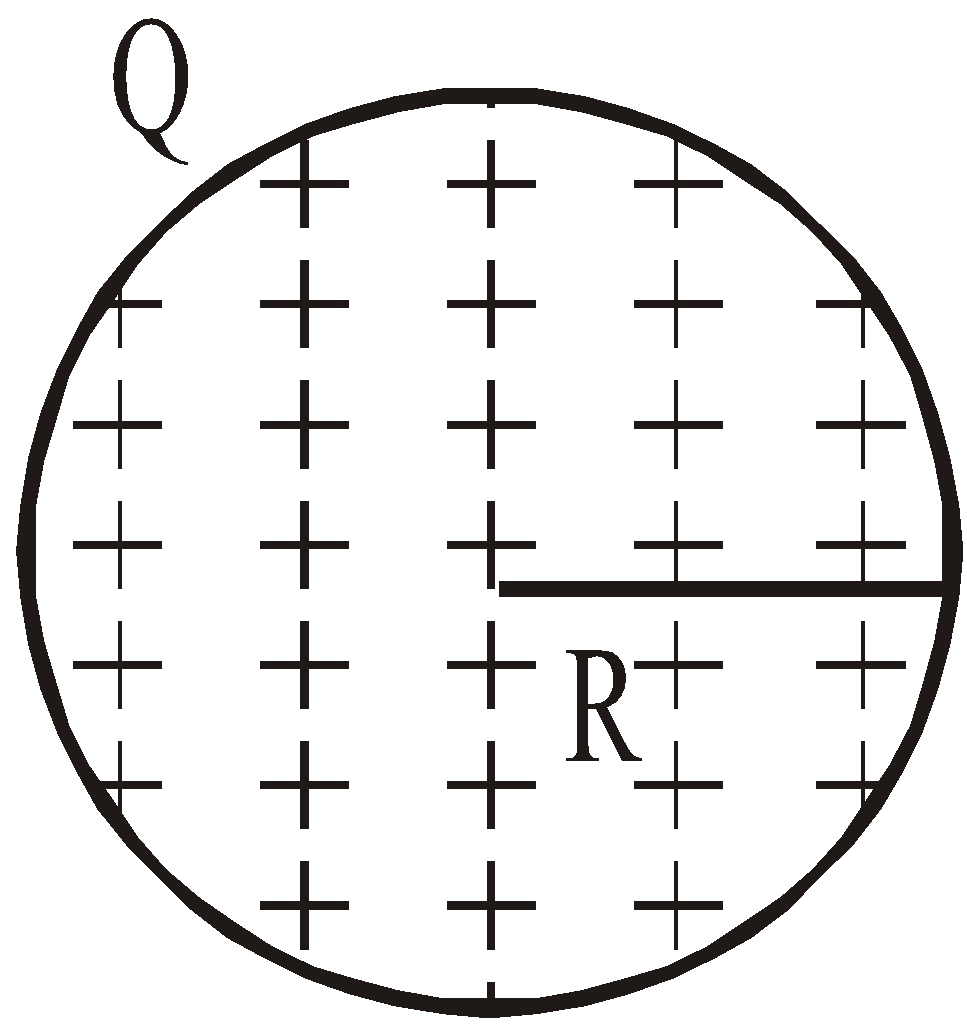
- Due to a spherical shell of uniformly distributed charge with surface charge density σ
- Due to a solid sphere of uniformly distributed charge with volume charge density ρ.
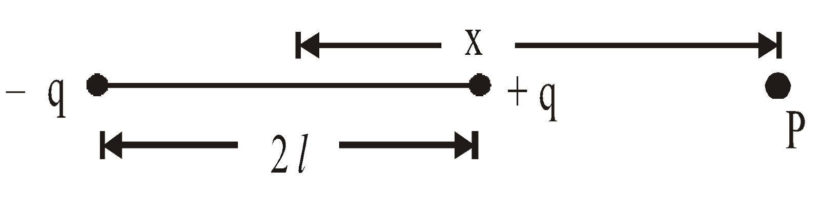
POTENTIAL DUE TO ELECTRIC DIPOLE
- Along axial line :
- Along equatorial line : Veq = zero
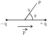
- At any point from the dipole :
KEEP IN MEMORY
- Electric field inside a charged conductor is zero
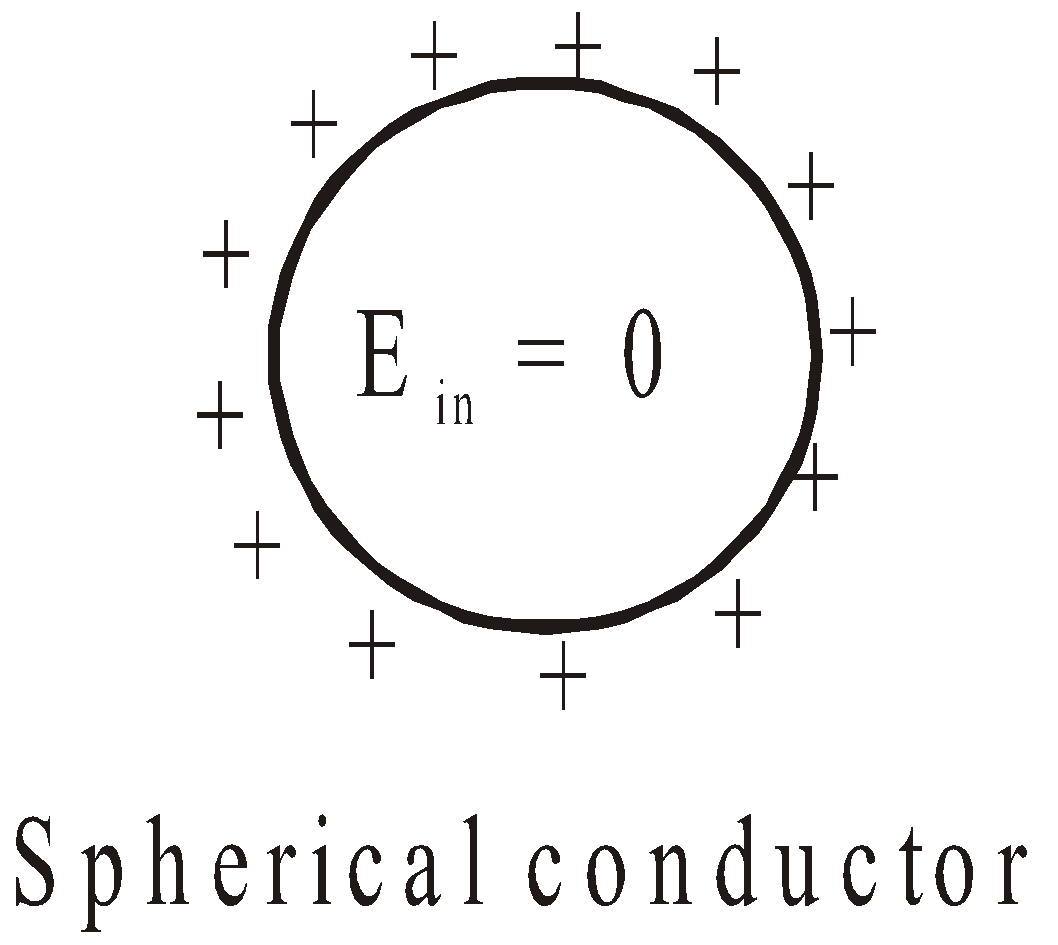
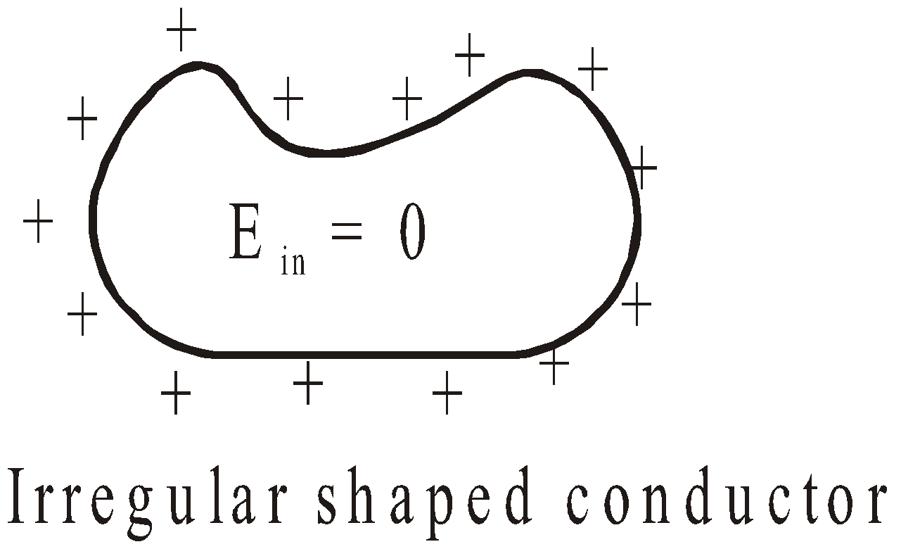
But in both the cases the potential at all the points of the surface will remain the same. But charges will have same distribution on spherical conductor and in case of irregularly shaped conductor the charge distribution will be non-uniform. At sharp points, charge density has greatest value.
- Electronic lines of force are always perpendicular to the equipotential surfaces.
- The work done in moving a charge from a point to the other on an equipotential surface is zero as the potential difference between the two points is zero.
- The electric potential at a point due to a point charge decreases (or increases) by K-times if the distance between the charge and the point increases (or decreases) by K-times.
- A ring with a charge distribution behaves as a point charge for the points very far from its centre.
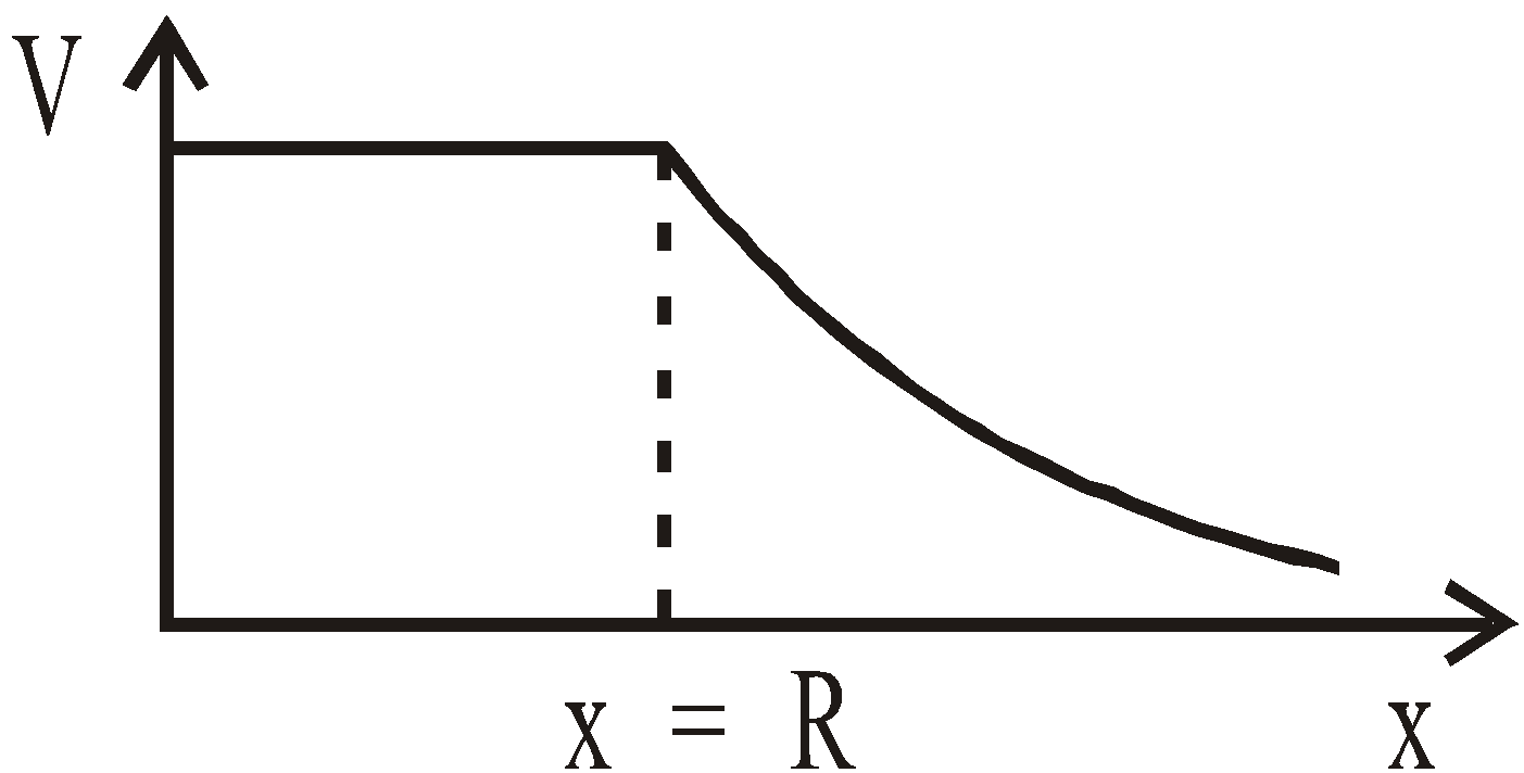
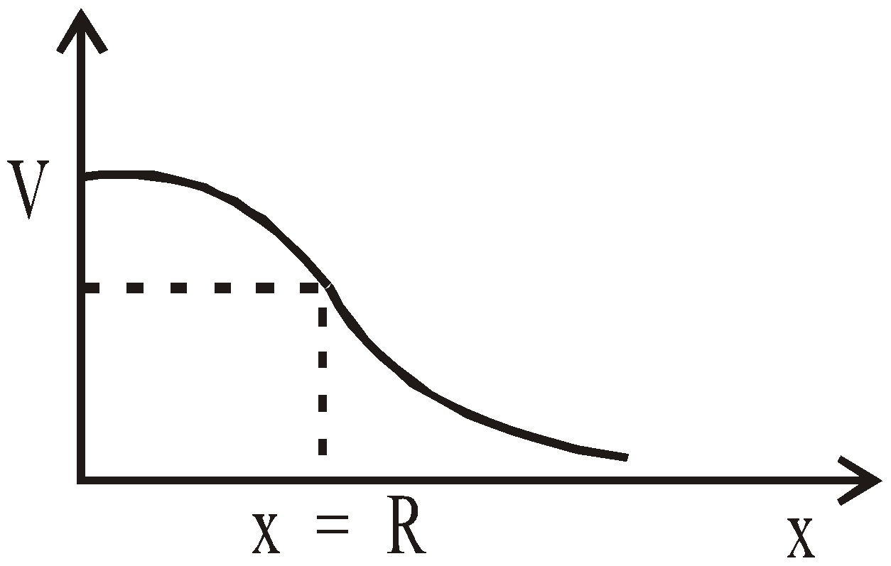
- The electric potential is constant inside a hollow charged sphere and it is also equal to its value on the surface but it varies inversely with the distance outside the sphere.
- The electric potential at points inside a solid sphere has a non-zero value and decreases as we go from the centre outwards. It behaves as a point charge for the points outside the sphere.
- The electric potential at a point due to a dipole varies directly with the dipole moment.
COMMON DEFAULT
Incorrect : Where electric field is zero, electric potential is also zero.
Correct : It is not always correct, for example in a charged conducting shell, electric field inside the shell E = 0 but potential is not zero.
Incorrect : Where electric potential is zero, electric field is also zero.
Correct : It is not always correct. In the case of equatorial plane of an electric dipole the electric potential is zero but the electric field is non-zero.
ELECTROSTATICS OF CONDUCTORS
Conductor is a substance that can be used to carry or conduct electric charges. Metals like silver. Copper, aluminium etc. are good conductors of electricity.
Regarding electrostatics of conductors following points are worth noting.
- Inside a conductor, electric field is zero.
- The interior of a conductor can have no excess charge in static situation.
- Electric field at the surface of a charged conductor is

where, s = surface charge density
- Electric field just outside a charged conductor is perpendicular to the surface of the conductor at every point.
- Electrostatic potential is constant throughout the volume of the conductor and has the same value as on its surface.
- Surface density of charge is different at different points.
CAPACITORS AND CAPACITANCE
A capacitor or condenser is a device that stores electrical energy. It generally consists of two conductors carrying equal but opposite charges.
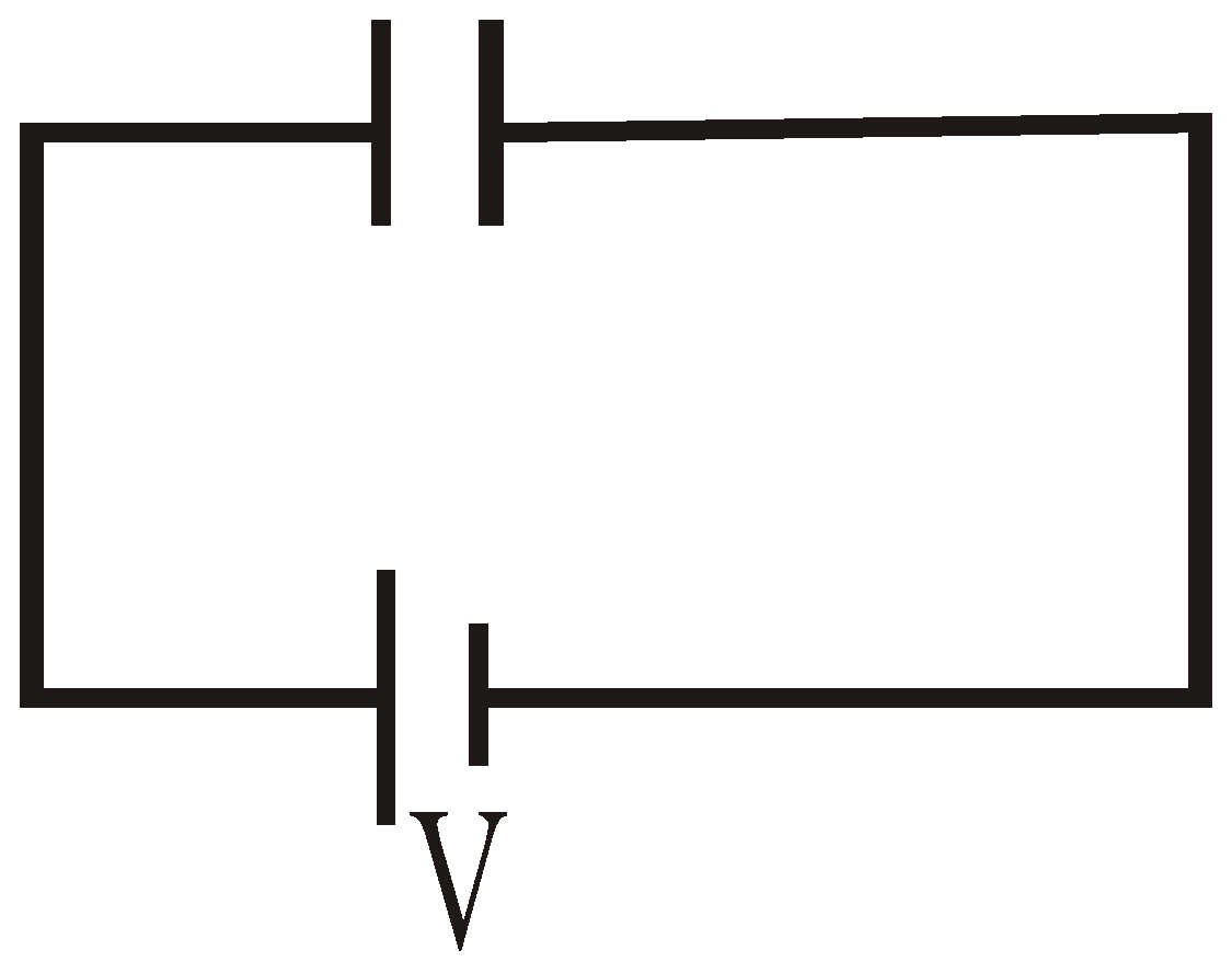
The ability of a capacitor to hold a charge is measured by a quantity called the capacitance. Let us consider two uncharged identical conductors X and Y and create a P.D. (Potential Difference) V between them by connecting with battery B as shown in figure.
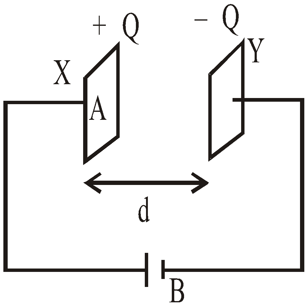
Fig- A capacitor consists of electrically insulated conductors carrying equal positive and negative charge
After connection with the battery, the two conductors X and Y have equal but opposite charges. Such a combination of charged conductors is a device called a capacitor. The P.D. between X and Y is found to be proportional to the charge Q on capacitor.
The capacitance C, of a capacitor is defined as the ratio of the magnitude of the charge on either conductor to the magnitude of P.D. between them.
Capacitance is always a positive quantity.
The S.I. unit of capacitance is coulomb per volt or farad (F).
Furthermore, the value of capacitance depends on size, shape, relative positions of plate, and the medium between the plates. The value of C does not depend on the charge of the plate or p.d. between the plates.
ENERGY STORED IN A CAPACITOR
If Q is charge, V is p.d, C is the capacitance of the capacitor then the energy stored is 
SHARING OF CHARGES
When the two charged conductors of capacitances C1 and C2 at potentials V1 and V2 respectively, are connected by a conducting wire, the charge flows from higher to lower potential, until the potentials of the two conductors are equal.
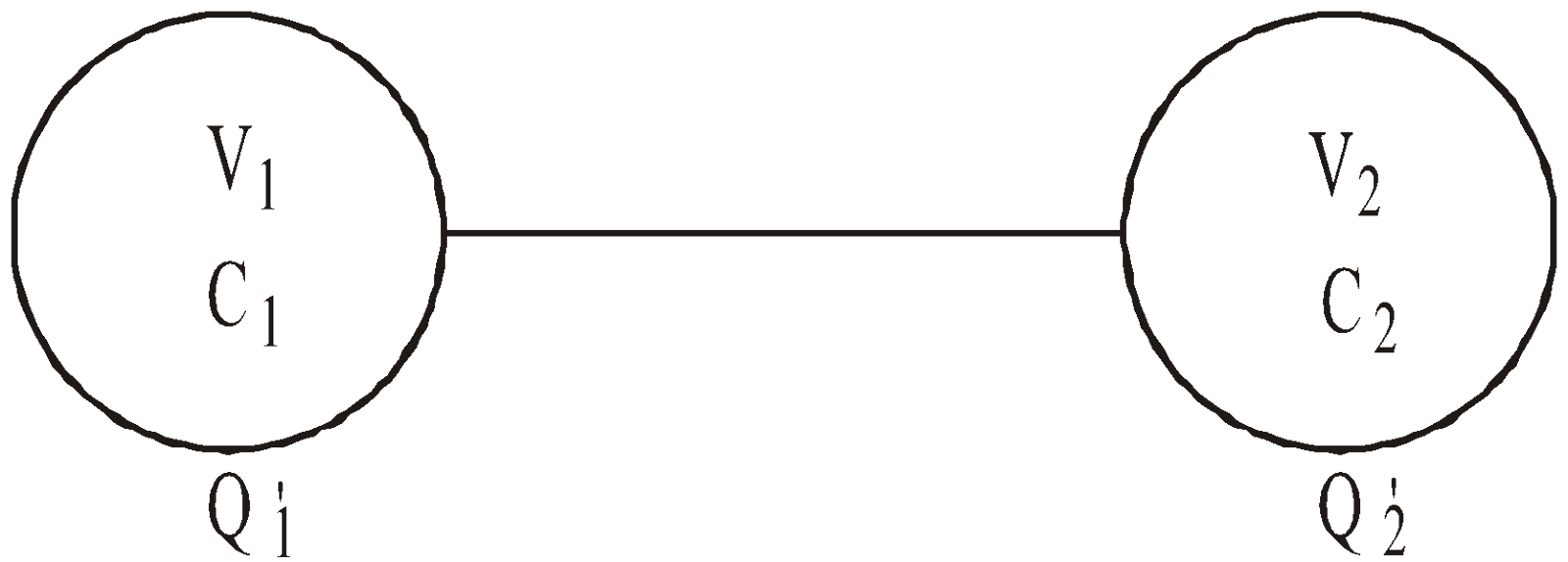
The common potential after sharing of charges,
The charges after sharing on two conductors will be
There is a loss of energy during sharing, converted to heat given by

PARALLEL PLATE CAPACITOR
It consists of two parallel metallic plates of any shape, each of area A and at a distance d apart.
The capacitance of the capacitor is given by 
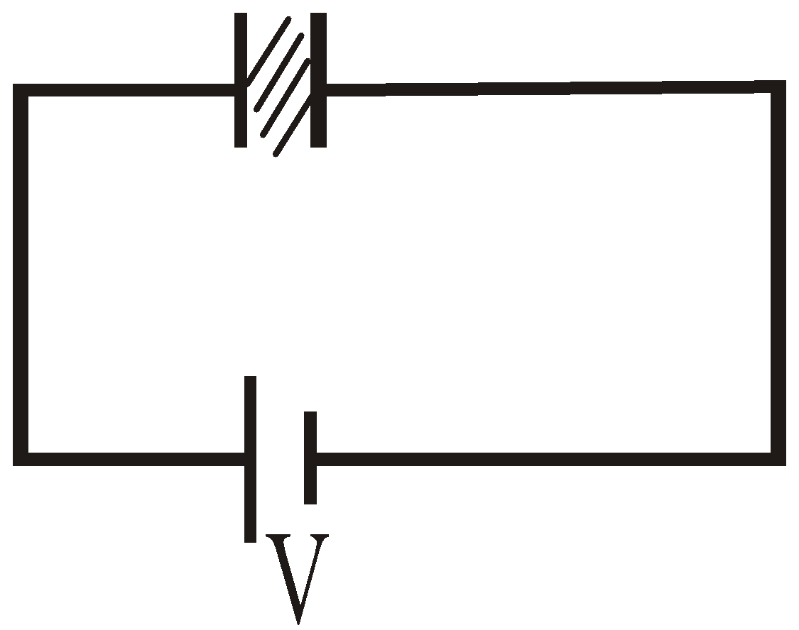
EFFECT OF DIELECTRIC ON CAPACITANCE
When a dielectric slab is placed between the plates of a parallel plate capacitor, the charge induced on its plates due to polarisation of dielectric is 
where K = dielectric constant.
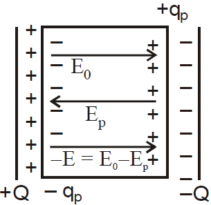
When an electric field is applied across a dielectric, induced charges appear on the surface of dielectric which is shown in the above figure. These induced charges produce their own field which acts in the opposite direction of the applied field. Hence, total field is reduced, i.e., E0 = Ep – E where E0 is the applied field, Ep is the induced field and E is the resultant field.
E is given by , where K is the dielectric constant.
If medium between the plates is having a dielectric of dielectric constant K then the capacitance is given 
If the space between the plates is partly filled with dielectric then the capacitance of the capacitor will be given by,
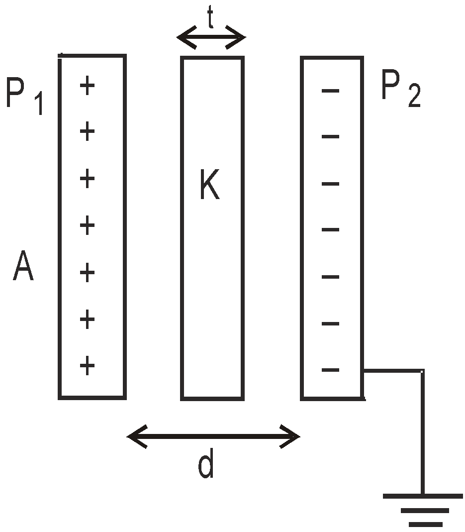
 ,
, where t is the thickness of the dielectric with dielectric constant K.
KEEP IN MEMORY
- The unit farad is quite a big unit for practical purposes. Even the capacitance of a huge body like earth is 711 μF.
- A capacitor is a device which stores charges and produces electricity whenever required.
- If the two plates of a capacitor is connected with a conducting wire, sparking takes place which shows that electrical energy is converted into heat and light energy.
- A capacitor allows A.C. but doesn’t allow D.C. to pass through it.
- The capacitance of a capacitor increases with insertion of a dielectric between its plates and decreases with increase in the separation between the plates.
- The capacitance of a capacitor increases K times if a medium of dielectric constant K is inserted between its plates.
- The energy of a capacitor for a particular separation between the plates is the amount of work done in separating the two plates to that separation if they are made to touch to each other.
- The loss of energy when the two charged conductors are connected by a wire doesn’t depend on the length of the wire.
SPHERICAL CAPACITOR
It consists of two concentric spherical conductors of radii R1 and R2. The space between two conductors is filled by a dielectric of dielectric constant K.
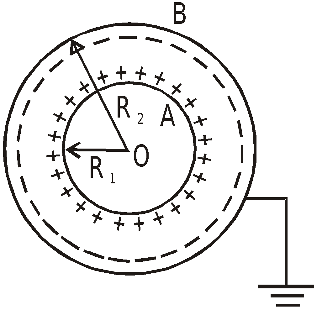
- When outer conductor is earthed,
Capacitance of spherical capacitor,
- When inner sphere is earthed,
This is because the combination behaves as two capacitors in parallel, one is a capacitor formed by two concentric spherical shells and the other is an isolated spherical shell of radius R2.
CYLINDRICAL CAPACITOR
It consists of two-coaxial cylindrical conductors of radii R1 and R2, the outer surface of outer conductor being earthed. The space between the two is filled with a dielectric of dielectric constant K.
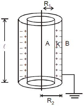
The capacitance of cylindrical condenser of length l
 (without dielectric)
 (with dielectric)
COMBINATION OF CAPACITORS
SERIES COMBINATION
- In this combination, the positive plate of one capacitor is connected to the negative plate of the other.
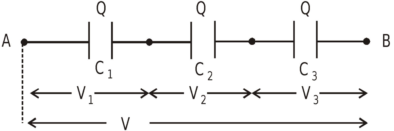
- The charges of individual capacitor are equal.
- The potential difference is shared by the capacitors in the inverse ratio of their capacities
i.e. Q = C1V1 = C2 V2 = C3 V3
Hence V = V1 + V2 + V3
- The equivalent capacitance (C) between A and B is
PARALLEL COMBINATION
- In this arrangement, +ve plates of all the condensers are connected to one point and negative plates of all the condensers are connected to the other point.
- The Potential difference across the individual capacitor is same.
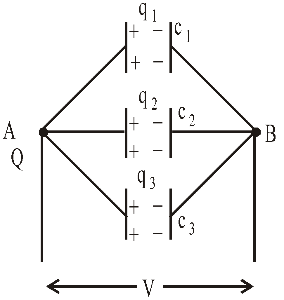
- The total charge shared by the individual capacitor is in direct ratio of their capacities
i.e.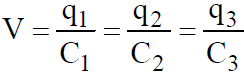
Hence, Q = q1 + q2 + q3
- The equivalent capacitance between a and b is ceq = c1 + c2 + c3 + ……..+ cn
KEEP IN MEMORY
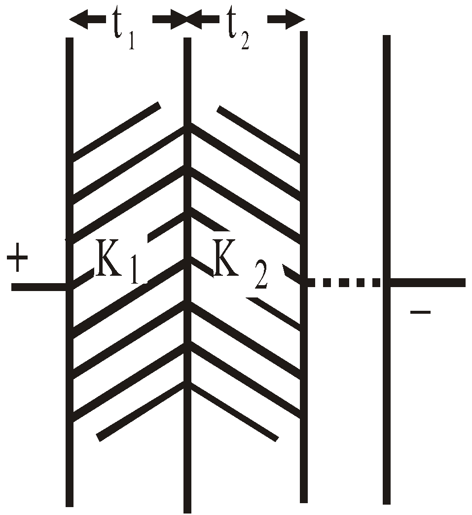
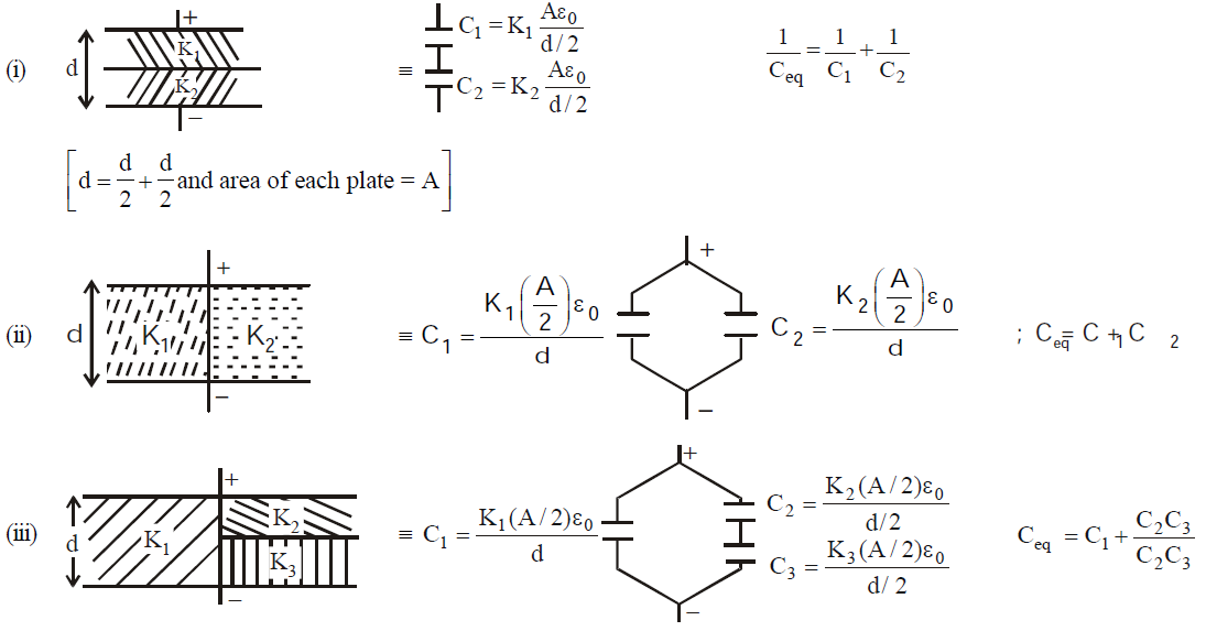
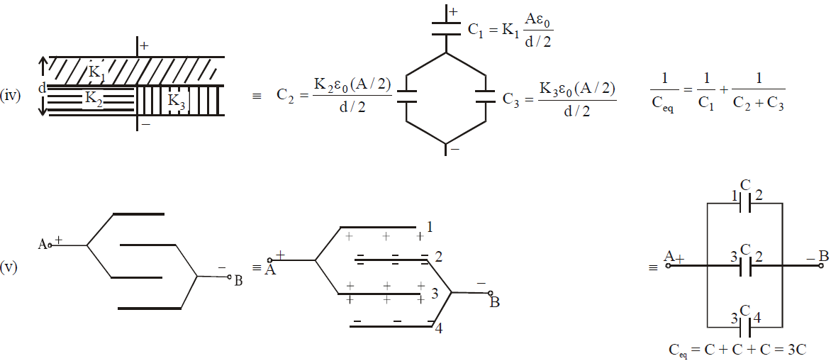
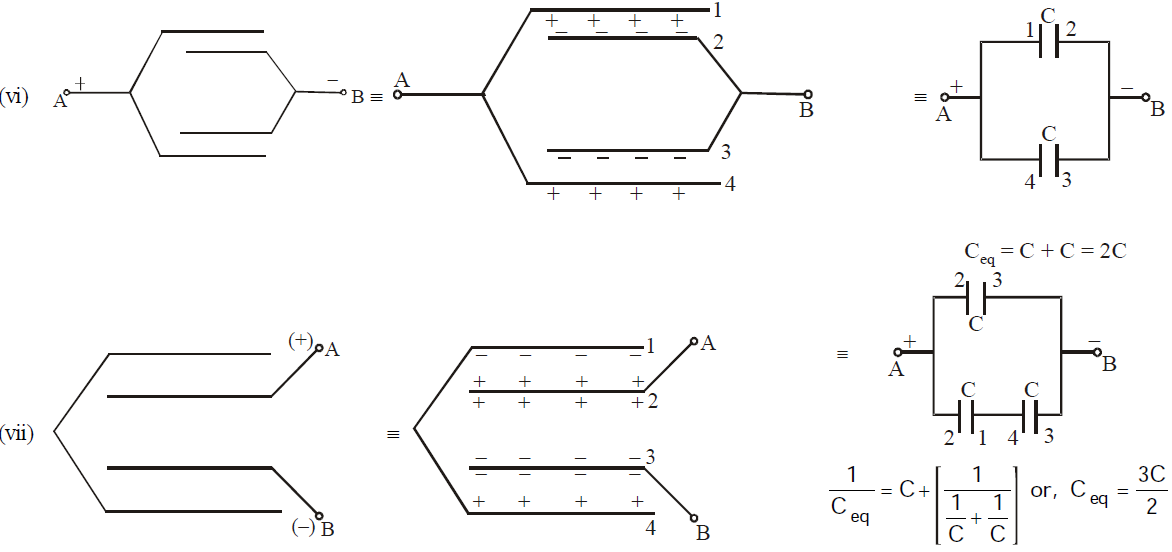
- The capacitance of a parallel plate capacitor having a number of slabs of thickness t1, t2, t3 …. and dielectric constant K1, K2, K3 …. respectively between the plates is

- When a number of dielectric slabs of same thickness (d) and different areas of cross-section A1, A2, A3 … having dielectric constants K1, K2, K3, …. respectively are placed between the plates of a parallel plate capacitor then the capacitance is given by

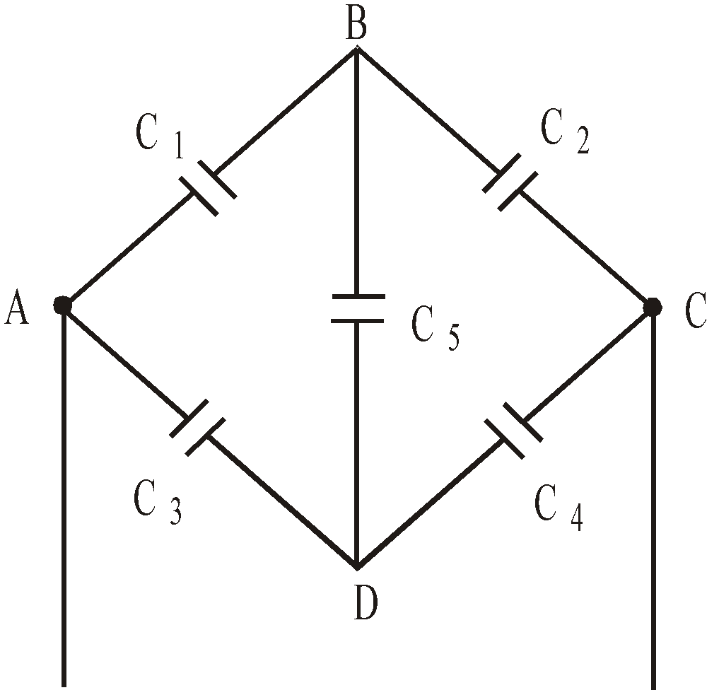
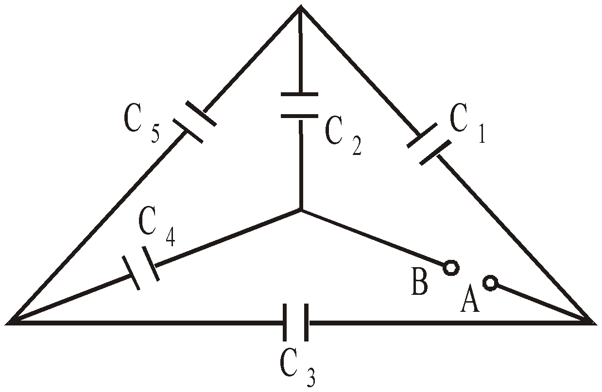
- When five capacitors are connected in wheatstone bridge arrangement as shown, such that
 , the bridge is balanced and C5 becomes ineffective. No charge is stored on C5. Therefore C1, C2 and C3, C4 are in series. The two series combinations are in parallel between A and C. Hence equivalent capacitance can be calculated.
RELATION BETWEEN THREE ELECTRIC VECTORS
If an electric field E is applied across a parallel plate capacitor filled with a dielectric of dielectric constant K (or permittivity ε), then
Polarisation P = induced charge per unit area (opposite to free charge) = 
Electric displacement D = εE = εo E + P
i.e. Polarisation P = (ε – εo) E = (Kεo – εo) E
Electric susceptibility, 
Relation between dielectric constant K and electric susceptibility χe
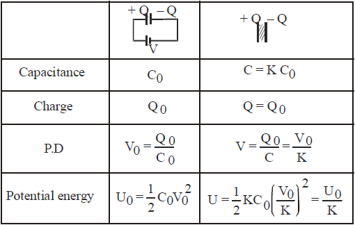
EFFECT OF FILLING DIELECTRIC WITH BATTERY CONNECTED
When there is no dielectric
Capacitance 
Potential difference between the plates V
Charge on a plate Q = CV
Energy 
Electric field 
When dielectric is inserted
Q = K C0 V = KQ0
EFFECT OF FILLING A DIELECTRIC IN A CAPACITOR AFTER DISCONNECTION OF BATTERY
CHARGING AND DISCHARGING A CAPACITOR
CHARGING A CAPACITOR
When an uncharged capacitor is connected across a source of constant potential difference such as a cell, it takes a finite time to get fully charged, although this time interval may be small. This time-interval depends on the capacity of the capacitor and the resistance in the circuit.
DURING THE PERIOD OF CHARGING
- The charge on the capacitor increases from ‘zero’ to the final steady charge.
- The potential difference developed across the capacitor opposes the constant potential difference of the source.
- The charge on the capacitor ‘grows’ only as long as the potential difference of source is greater than the potential difference across the capacitor. This transport of the charge from the source to the capacitor constitutes a transient current in the circuit.
- As the charge on the capacitor increases, more energy is stored in the capacitor.
- When the capacitor is fully charged, potential difference across the capacitor is equal to the potential difference of the source and the transient current tends to zero.
If V0 = constant potential difference of the source
R = pure resistance in the circuit
C = capacity of the capacitor
Q0 = final charge on the capacitor, when fully charged
q = charge on the capacitor at time ‘t’ from the starting of the charging
V = potential difference across the capacitor at time ‘t’
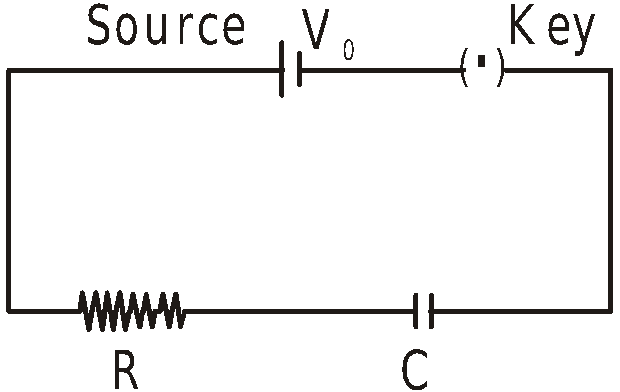
Then 
and i = current in the circuit at time ‘t’ = 
At time ‘t’ by Kirchhoff’s law
i.e.
Integrating and putting in the initial condition q = 0 at t = 0, we get

Special cases :
- At t = 0, q = 0.
- When t increases, q increases.
- As


- At t = CR [‘CR’ has dimensions of time]
This value of t = CR is called the ‘time constant’ of the (CR) circuit.
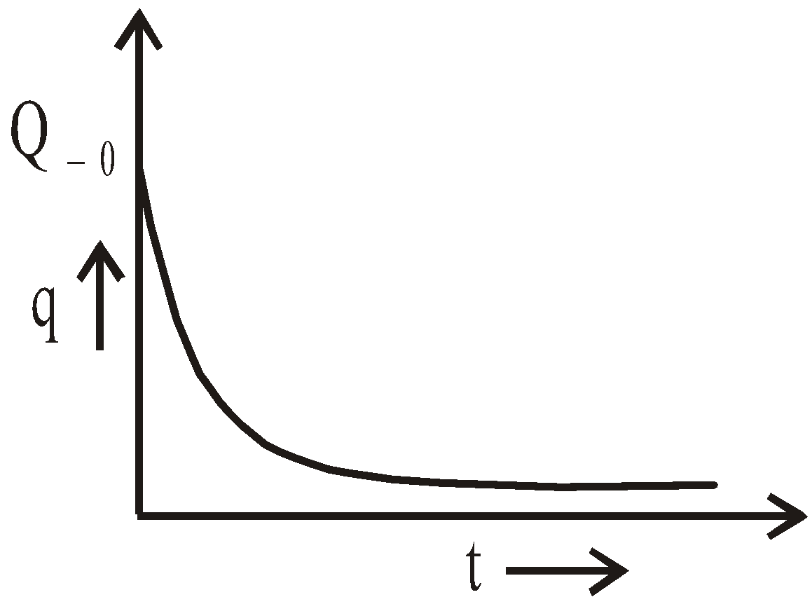
DISCHARGING OF A CAPACITOR
If after charging the capacitor, the source of constant potential difference is disconnected and the charged capacitor is shorted through a resistance ‘R’, then by Kirchhoff’s law, at time ‘t’ from the instant of shorting,
Putting,
- the initial condition, q = Q0 at t = 0 and
- the final condition, q = 0 at ,

the solution to the above equation is 
KEEP IN MEMORY
- If n small drops each having a charge q, capacity ‘C’ and potential V coalesce to form a big drop, then
- the charge on the big drop = nq
- capacity of big drop = n1/3 C
- potential of big drop = n2/3 V
- potential energy of big drop = n5/3 U
- surface density of charge on the big drop = n1/3 × surface density of charge on one small drop.
- Charged soap bubble : Four types of pressure act on a charged soap bubble.
- Pressure due to air outside the bubble PO, acting inwards.
- Pressure due to surface tension of soap solution PT, acting inwards.
- Pressure due to air inside the bubble, Pi, acting outwards.
- Electric pressure due to charging, Pe =
 , acting outwards.
In equilibrium, Pi + Pe = PO + PT
or, Pi – PO = PT – Pe
or, Pexcess = PT – Pe
∴
Where T = surface tension of soap solution,
σ = surface charge density of bubble.
If Pi = PO then Pi – PO = PT – Pe = 0 or PT = Pe

Hence for maintaining the equilibrium of charged soap bubble,


- Force of attraction between the plates of a parallel plate capacitor =

where, A = area of the plates of capacitor, K = dielectric constant of the medium filled between the plates.
In terms of electric field, the force of attraction 
- Uses of capacitor :
- In LC oscillators
- As filter circuits
- Tuner circuit in radio etc.
- The total energy stored in an array of capacitors (in series or in parallel) is the sum of the individual energies stored in each capacitor.
COMBINATION OF CAPACITOR : EQUIVALENT CAPACITANCE
SOME METHODS OF FINDING EQUIVALENT CAPACITANCE
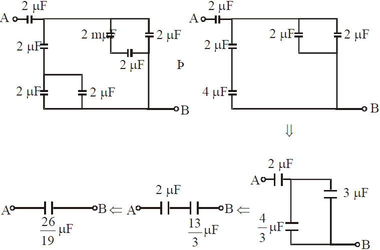
METHOD 1 : Successive Reduction
This method is applicable only when the capacitor can be clearly identified as in series or in parallel.
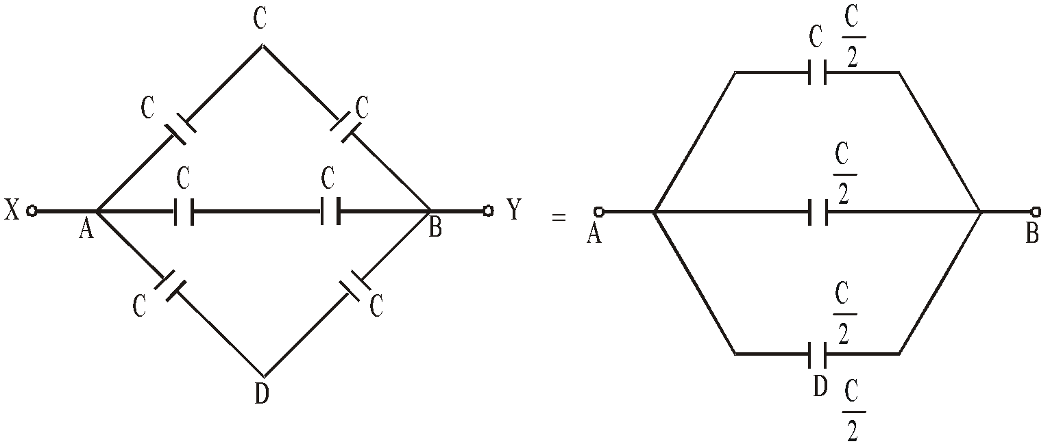
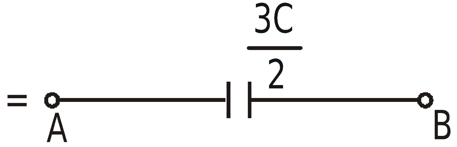
METHOD 2 : Using Symmetry
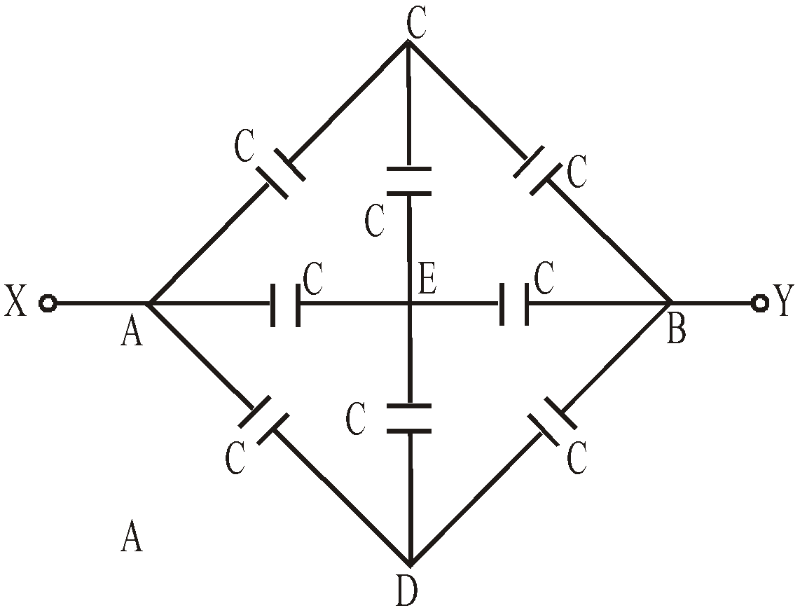
The above circuit is symmetrical about XAEBY axis. This is because the upper part of the circuit is mirror image of lower part.
Therefore VC = VE = VD. The circuit can be redrawn as
METHOD 3 : Wheatstone bridge
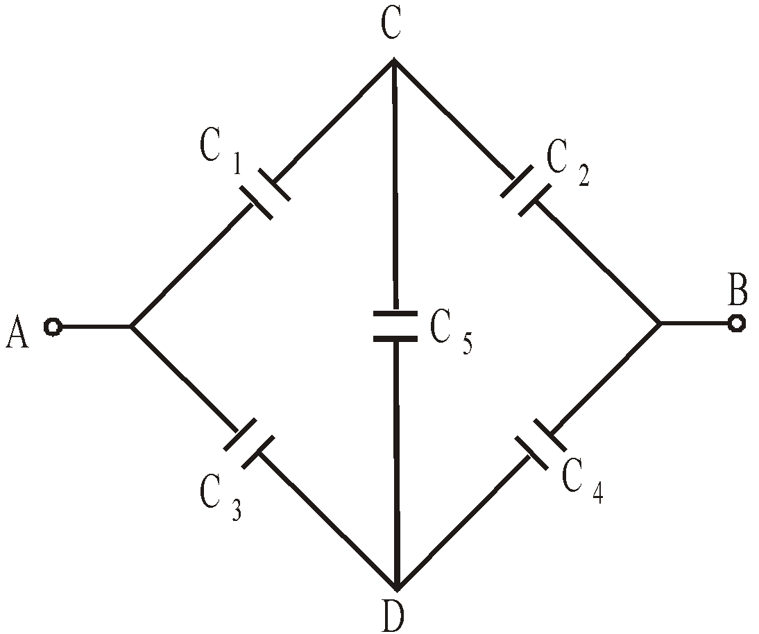
If  then the wheatstone bridge is balanced. In this case there will be no charge accumulation in C5 when battery is attached across A and B. Therefore the equivalent circuit is the capacitance C1 and C2 are in series. Similarly C3 and C4 is in series. Therefore the equivalent capacitance occurs between A and B is
The other forms of wheatstone bridge are :
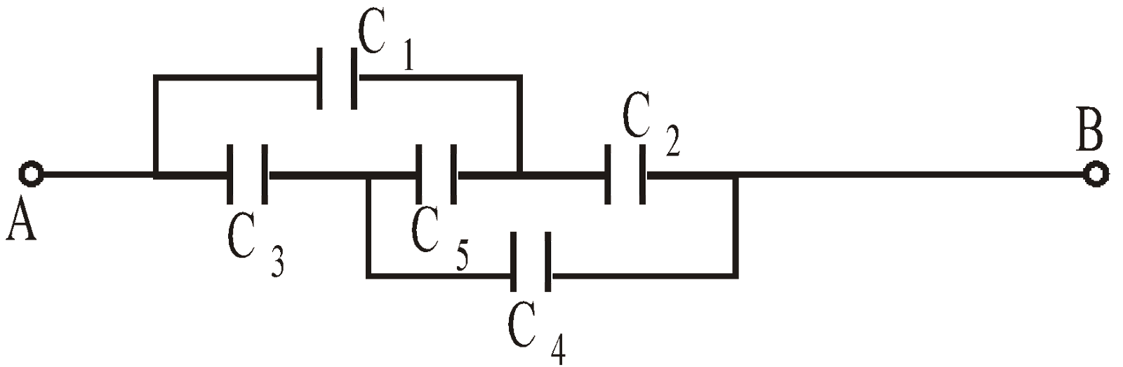
or
METHOD 4 : If none of the above method works, then we can use the method of Kirchhoff’s laws – junction law and loop law.
SHARP POINT ACTION (CORONA DISCHARGE)
When the electric field on a point on the surface of a conductor exceeds the electric strength of air, then the air becomes conducting and the surface of conductor loses charge. This action occurs usually at the sharp points of a conductor as here σ is high, thus creating high electric field. This phenomenon is also called corona discharge.
VAN DE GRAAF GENERATOR
R.J. Van de Graff in 1931 designed an electrostatic generator capable of generating very high potential of the order of 5 × 10⁶ V, which was then made use of an accelerating charged particles so as to carry out nuclear reactions.
Principle : When a charged conductor is placed in contact with the inside of a hollow conductor, all of the charge of first conductor is transferred to the hollow conductor. i.e., the charge on hollow conductor or its potential can be increased by any limit by repeating that processes.
The basic fact of Van de Graaf generator is described in fig. (Charge is delivered continuously to a high voltage electrode on a moving belt of insulating material).
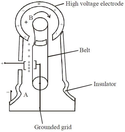
Schematic diagram of a Van de Graaf generator.
Charge is transferred to hollow conductor at the top by means of a rotating belt. The charge is deposited on the belt at point A and is transferred to hollow conductor at point B.
The high voltage electrode is a hollow conductor mounted on an insulating medium. The belt is charged at A by means of corona discharge between comb-like metallic needles and a grounded grid. The needles are maintained at a positive potential of typically 104 eV. The positive charge on the moving belt is transferred to the high voltage electrode by second comb of needles at B.
Since the electric field inside the hollow conductor is negligible, the positive charge on the belt easily transfers to the high- voltage electrode, regardless of its potential. We can increase the potential of the high voltage electrode until electrical discharge occur through the air. The “breakdown” voltage of air is about 3 × 10 6 V/m.