▶️ Answer/Explanation
(a)
Sound waves require a medium to propagate (mechanical waves), whereas electromagnetic waves can propagate in a vacuum. Alternatively, the speed of sound is much lower than the speed of electromagnetic waves.
(b)
(i) \(\lambda = \frac{v}{f} = \frac{340}{1700} = 0.20\,m\).
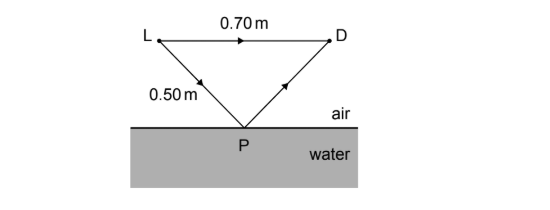
(ii) Calculate path difference: Path LPD \(= 0.50 + 0.50 = 1.00\,m\). Path LD \(= 0.70\,m\).
Path difference \(= 1.00 – 0.70 = 0.30\,m\).
Phase difference in wavelengths: \(\frac{0.30}{0.20} = 1.5\lambda\).
Since the path difference is \((n + 0.5)\lambda\) (specifically \(1.5\lambda\)), the waves meet out of phase, causing destructive interference.
(c)
Calculate the angle of incidence \(\theta_1\). From geometry, \(\sin \theta_1 = \frac{0.35}{0.50} = 0.70\) (\(\theta_1 \approx 44^\circ\)).
Check for refraction using Snell’s Law: \(\frac{\sin \theta_1}{v_1} = \frac{\sin \theta_2}{v_2}\).
\(\sin \theta_2 = \frac{1500}{340} \times 0.70 \approx 3.1\).
Since \(\sin \theta_2 > 1\), refraction is not possible. Total internal reflection occurs, so the sound cannot enter the water.