
Question 1
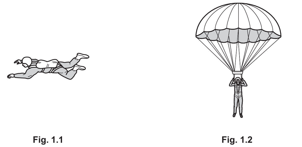
Fig. 1.1 shows the skydiver falling freely with her parachute closed.
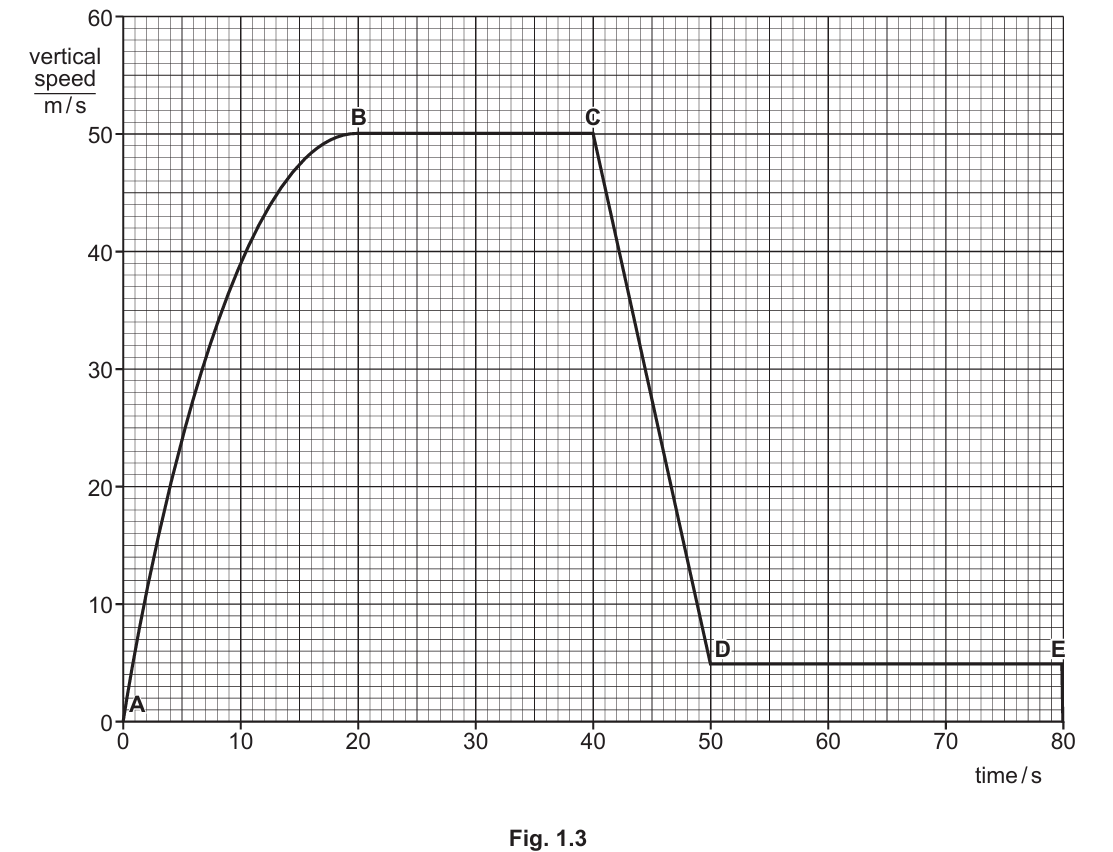
Fig. 1.2 shows the skydiver falling with the parachute open.
The weight of the skydiver acts downwards.
While the skydiver is falling, another force acts upwards.
The upward force varies as the skydiver falls.
Most-appropriate topic codes (Cambridge IGCSE Physics 0625):
• Topic $1.2$ — Motion
• Topic $1.5.1$ — Effects of forces
▶️ Answer/Explanation
(a)(i)
For the correct answer:
Accelerating / increasing speed.
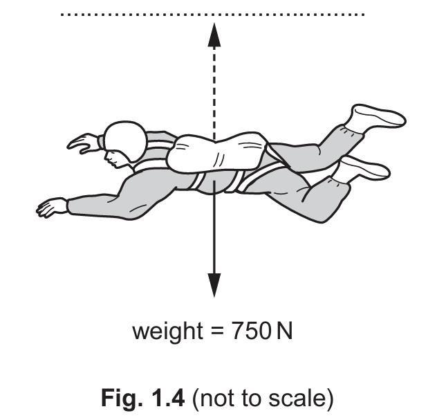
Looking at the speed–time graph between $t = 0$ and $t = 20\text{ s}$, the curve rises steadily from zero, which tells us that the skydiver’s speed is continuously increasing over this interval. When speed increases with time on a speed–time graph, the object is said to be accelerating. At this early stage of the fall, the parachute is still closed and gravity is pulling the skydiver downward. Although air resistance also acts upward, it is not yet large enough to balance the weight, so there is a net downward force causing this acceleration. The motion is therefore best described as accelerating or increasing in speed throughout this entire 20-second period.
(a)(ii)
For the correct answer:
$50\text{ m/s}$
The maximum vertical speed can be read directly from the highest point on the speed–time graph in Fig. 1.3. The graph reaches its peak value before the sudden sharp drop that occurs when the parachute opens. Reading across from this highest point to the vertical axis gives a speed of $50\text{ m/s}$. This maximum speed is also known as the first terminal velocity — the point at which air resistance has grown large enough to exactly equal the skydiver’s weight of $750\text{ N}$, so there is no longer any net force and the speed stops increasing. Beyond this point the graph either remains flat or drops sharply due to the parachute opening.
(a)(iii)
For the correct answer:
C
When a parachute opens, the surface area of the skydiver exposed to the air increases enormously in a very short time. This causes the air resistance (drag) to shoot up almost instantaneously to a value far greater than the skydiver’s weight, producing a strong net upward force. On the speed–time graph, this effect appears as a sudden, steep drop in speed. Point C is the location on the graph where exactly this kind of sharp, dramatic decrease in speed begins, making it the most logical point at which the parachute was opened. All other labelled points show either increasing speed or relatively gentle changes, not the abrupt deceleration characteristic of a parachute deployment.
(a)(iv)
For the correct answer:
$150\text{ m}$
On a speed–time graph, the distance travelled during any time interval is equal to the area enclosed under the graph line for that interval. Between $t = 50\text{ s}$ and $t = 80\text{ s}$, the graph shows a perfectly horizontal line, meaning the skydiver is moving at a constant speed of $5\text{ m/s}$ — this is her second terminal velocity after the parachute has fully opened and stabilised. The area under this horizontal section forms a rectangle with a width (time) of $80 – 50 = 30\text{ s}$ and a height (speed) of $5\text{ m/s}$. Multiplying these together: $30 \times 5 = 150\text{ m}$, so the skydiver falls $150\text{ m}$ during this 30-second period.
(b)(i)
For the correct answer:
Friction / air resistance / drag.
As the skydiver moves downward through the air, she collides continuously with air molecules. These collisions exert a force on her body directed opposite to her motion, i.e., upward. This force is called air resistance, and it is a specific type of frictional force that acts on objects moving through a fluid such as air or water. It is also commonly referred to as drag in physics. The magnitude of this force is not constant — it increases as the skydiver’s speed increases, because at higher speeds she strikes more air molecules per second. This is why she eventually reaches a terminal velocity rather than accelerating indefinitely.
(b)(ii)
For the correct answer:
Any value greater than $0\text{ N}$ and less than $750\text{ N}$.
At $t = 10\text{ s}$, we can see from the graph that the skydiver’s speed is still increasing, which means she is still accelerating downward. For acceleration to be occurring in the downward direction, Newton’s second law tells us that there must be a net downward force — in other words, the weight must be greater than the upward air resistance. Since her weight is $750\text{ N}$, the air resistance at this moment must be less than $750\text{ N}$. At the same time, she is already moving and air resistance always exists when there is motion through a fluid, so the force cannot be zero either. Therefore, any value between $0\text{ N}$ and $750\text{ N}$ (exclusive) is an acceptable answer for the upward force at $t = 10\text{ s}$.
(b)(iii)
For the correct answer:
$750\text{ N}$
At $t = 30\text{ s}$, the speed–time graph shows that the skydiver is travelling at a constant speed — the graph is horizontal at this point. According to Newton’s first law, an object moving at constant velocity has zero net force acting on it, meaning all forces are balanced. The two forces acting on the skydiver are her weight of $750\text{ N}$ downward and air resistance upward. For these to be in balance and produce zero net force, the upward air resistance must be exactly equal to the downward weight. Therefore, the upward force (air resistance) at $t = 30\text{ s}$ is precisely $750\text{ N}$.
(c)
For the correct answer:
$75\text{ kg}$
The relationship between weight, mass, and gravitational field strength is given by the equation $W = mg$, where $W$ is the weight in newtons, $m$ is the mass in kilograms, and $g$ is the gravitational field strength, taken as $10\text{ N/kg}$ on Earth. Rearranging this formula to find mass gives $m = W / g$. Substituting the known values: $m = 750 / 10 = 75\text{ kg}$. It is important to note that weight and mass are different quantities — weight is a force measured in newtons, while mass is the amount of matter in an object measured in kilograms and does not change with location. The skydiver’s mass is therefore $75\text{ kg}$.
Question 2
Most-appropriate topic codes (Cambridge IGCSE Physics 0625):
• Topic $1.8$ — Pressure
▶️ Answer/Explanation
(a)(i)
For the correct answer:
(Mercury/U-tube) manometer.
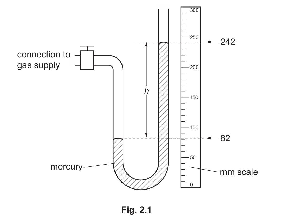
The device shown in Fig. 2.1 is a manometer, specifically a U-tube manometer filled with mercury. It consists of a U-shaped glass tube where one end is connected to the gas supply whose pressure is to be measured, and the other end is open to the atmosphere. The difference in the mercury levels between the two arms of the tube gives a direct indication of the pressure difference between the gas and the surrounding atmosphere. This instrument is widely used in physics and engineering because it provides a simple and reliable method of measuring gas pressures without requiring any mechanical components that could wear out over time.
(a)(ii)
For the correct answer:
$160\text{ mm}$
To find the difference $h$ between the two mercury levels, we read the scale positions of the mercury surface in each arm of the U-tube from Fig. 2.1 and subtract the lower reading from the higher one. From the diagram, the mercury level on the gas side sits at the lower position of $82\text{ mm}$, while the mercury on the open (atmospheric) side sits at the higher position of $242\text{ mm}$. Subtracting: $242 – 82 = 160\text{ mm}$. This height difference $h = 160\text{ mm}$ is significant because it directly represents the amount by which the gas pressure exceeds atmospheric pressure, expressed in millimetres of mercury.
(b)
For the correct answer:
$920\text{ mm}$ of mercury.
In a U-tube manometer connected to a gas supply, when the gas pressure is greater than atmospheric pressure, it pushes the mercury down on its side and up on the open side, creating the observed height difference. To find the absolute pressure of the gas, we add this height difference to the atmospheric pressure, because the gas must be supporting both the column of mercury of height $h$ and the atmosphere pressing down on the open end. Using the values: gas pressure $= 760 + 160 = 920\text{ mm}$ of mercury. This method of adding $h$ to atmospheric pressure only applies when the gas side is lower than the open side, confirming the gas pressure is above atmospheric.
(c)
For the correct answer:
Mercury is much denser than water, so the manometer would be impractically large if water were used instead.
Mercury is chosen as the liquid in a manometer primarily because of its exceptionally high density, which is approximately $13{,}600\text{ kg/m}^3$ — roughly 13.6 times denser than water. This high density means that even relatively large pressure differences only produce small, manageable differences in mercury column height, keeping the device compact and easy to use in a laboratory. If coloured water were used instead, its much lower density would require column height differences over 13 times greater to represent the same pressure, making the device extremely tall and completely impractical. Additionally, mercury does not wet glass, which means it forms a clear, easily readable meniscus, and it does not evaporate noticeably at room temperature, ensuring accurate and stable readings over time.
(d)
For the correct answer:
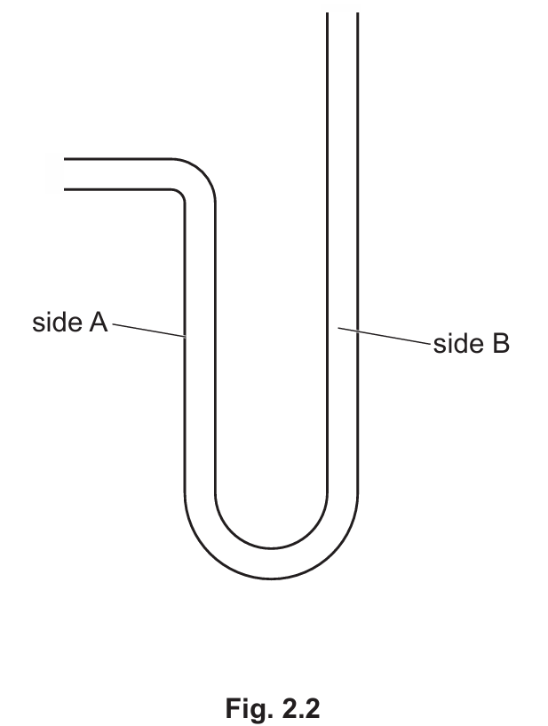
Mercury levels drawn at the exact same height on both sides A and B.
When the gas supply is turned off and the device is disconnected, both ends of the U-tube are now open to the atmosphere. This means that atmospheric pressure is acting equally downward on the mercury surface in both arm A and arm B simultaneously. Since the pressure pushing down on each side is identical, there is no longer any pressure difference between the two columns to cause a height difference. As a result, the mercury redistributes itself until the levels in both arms are exactly equal, settling at the same height. On Fig. 2.2, both mercury surfaces should therefore be drawn at the same horizontal level, with side A and side B clearly labelled at this common height.
Question 3
Most-appropriate topic codes (Cambridge IGCSE Physics 0625):
• Topic $2.2$ — Thermal properties and temperature
▶️ Answer/Explanation
(a)(i)
For the correct answer:
Place the thermometer in steam above pure boiling water at standard atmospheric pressure and check whether the liquid level aligns with the $100^{\circ}\text{C}$ mark.
To verify the accuracy of the $100^{\circ}\text{C}$ mark, the thermometer must be held in the steam that rises directly above pure water that is boiling at standard atmospheric pressure (101,325 Pa). It is important to position it in the steam rather than submerging it in the boiling water itself, as the steam temperature is more stable and uniform. If the thermometer is accurate, the liquid inside should rise to exactly align with the $100^{\circ}\text{C}$ graduation on the scale. Any deviation above or below this mark would indicate a calibration error. Using pure water is also essential, as dissolved impurities can slightly raise the boiling point and lead to an incorrect reading.
(a)(ii)
For the correct answer:
Place the thermometer in a mixture of pure melting ice and water and check whether the liquid level aligns with the $0^{\circ}\text{C}$ mark.
To check the $0^{\circ}\text{C}$ mark, the thermometer bulb is fully immersed in a beaker containing a well-stirred mixture of pure melting ice and water. This ice-water mixture maintains a steady temperature of exactly $0^{\circ}\text{C}$ as long as both ice and water are present together, because the energy absorbed from the surroundings is used to melt the ice rather than raise the temperature. The student should wait until the liquid column inside the thermometer stops moving and then check whether it sits exactly at the $0^{\circ}\text{C}$ graduation. Pure water and ice must be used, as any dissolved substances would lower the melting point and give an inaccurate fixed-point reading.
(a)(iii)
For the correct answer:
These two marks act as fixed points used for calibration, allowing the thermometer scale to be divided accurately and consistently.
The $0^{\circ}\text{C}$ and $100^{\circ}\text{C}$ marks are known as the lower fixed point and upper fixed point respectively, and they are the two fundamental reference temperatures upon which the entire Celsius scale is built. Once these two points are accurately established on the thermometer, the interval between them can be divided into 100 equal divisions, each representing $1^{\circ}\text{C}$. Without these standardised fixed points, thermometers made by different manufacturers would produce inconsistent readings and could not be meaningfully compared with one another. They essentially ensure that every correctly calibrated thermometer gives the same reading under the same physical conditions, which is the foundation of reliable scientific measurement.
(b)(i)
For the correct answer:
Volume expansion / contraction of the liquid.
In a liquid-in-glass thermometer, the physical property being exploited is the thermal expansion of the liquid contained inside the glass tube. When the temperature rises, the liquid — typically mercury or coloured alcohol — absorbs heat energy, causing its particles to move faster and spread further apart. This results in the liquid expanding and occupying a greater volume, which forces it to rise up the narrow capillary tube. Conversely, when the temperature falls, the liquid contracts and the column drops. The extent of this expansion or contraction is directly and consistently related to temperature, making it a reliable thermometric property for measuring temperature across the instrument’s range.
(b)(ii)
For the correct answer:
Electrical resistance / electromotive force (e.m.f.) / length of a solid.
Another physical property that varies reliably with temperature and can therefore be used to measure it is electrical resistance. In a resistance thermometer, a coil of pure metal wire (often platinum) is used, whose electrical resistance increases in a predictable and consistent way as the temperature rises. By measuring the resistance of the wire using a circuit, the corresponding temperature can be determined accurately. This type of thermometer is particularly useful for measuring very high or very low temperatures that are outside the range of a liquid-in-glass thermometer. Alternatively, the electromotive force (e.m.f.) generated at the junction of two different metals — as in a thermocouple — is another well-known thermometric property used in practical temperature measurement.
Question 4
Most-appropriate topic codes (Cambridge IGCSE Physics 0625):
• Topic $2.1.1$ — States of matter
• Topic $2.3.4$ — Consequences of energy transfer
▶️ Answer/Explanation
(a)(i)
For the correct answer:
Evaporation.
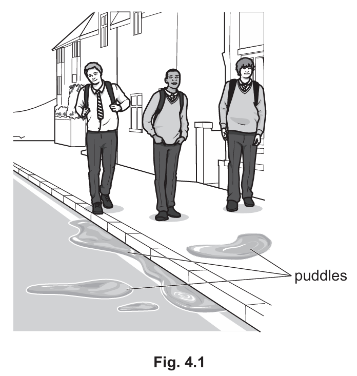
The process responsible for the puddles disappearing over the course of the school day is evaporation. This is the gradual conversion of a liquid into a gas or vapour that occurs at the surface of the liquid at temperatures below its boiling point. Unlike boiling, which takes place throughout the entire body of liquid at a fixed temperature, evaporation is a slow and continuous surface process that can happen at any temperature. Because the air is not saturated with water vapour and there is warmth from sunlight, the water molecules at the puddle’s surface are constantly escaping into the surrounding air, and over several hours the entire puddle disappears in this way.
(a)(ii)
For the correct answer:
At the surface, the more energetic molecules escape from the liquid by overcoming the intermolecular forces holding them in the liquid, turning from liquid into gas/vapour.
Within any liquid, the molecules are in constant random motion but do not all possess the same kinetic energy — there is a continuous distribution of speeds. At the surface of the puddle, some molecules happen to be moving fast enough in an upward direction to overcome the attractive intermolecular forces that bind them to the rest of the liquid. These high-energy molecules break free and escape into the air above as water vapour. Because it is specifically the most energetic molecules that leave, the average kinetic energy of the remaining molecules in the puddle decreases, which is why evaporation also causes the liquid to cool. Over time, more and more molecules escape in this manner until the puddle has completely evaporated.
(b)
For the correct answer:
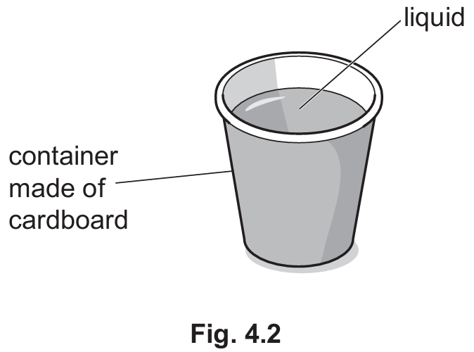
Suggestion 1: Surround the container with an insulating material such as foam, lagging, or cotton wool — this reduces heat loss by conduction.
Suggestion 2: Add a lid to the top of the container — this reduces heat loss by convection and evaporation.
The walls of a simple cardboard cup allow thermal energy to conduct outward directly through the material into the cooler surroundings. Wrapping the container in a thick layer of insulating material such as foam or cotton wool introduces a poor conductor between the hot liquid and the outside air, greatly reducing the rate of heat loss by conduction. Additionally, the open top of the container allows hot air and steam to rise and escape freely — this is convection — and also permits evaporation of the hot liquid from its surface, both of which carry significant amounts of thermal energy away. Fitting a well-insulated lid seals the top, trapping the warm air and preventing both convective heat loss and evaporative cooling simultaneously, making it the second highly effective improvement to the design.
Question 5

Most-appropriate topic codes (Cambridge IGCSE Physics 0625):
• Topic $3.1$ — General wave properties
• Topic $3.3$ — Electromagnetic spectrum
▶️ Answer/Explanation
(a)(i)
For the correct answer:
S
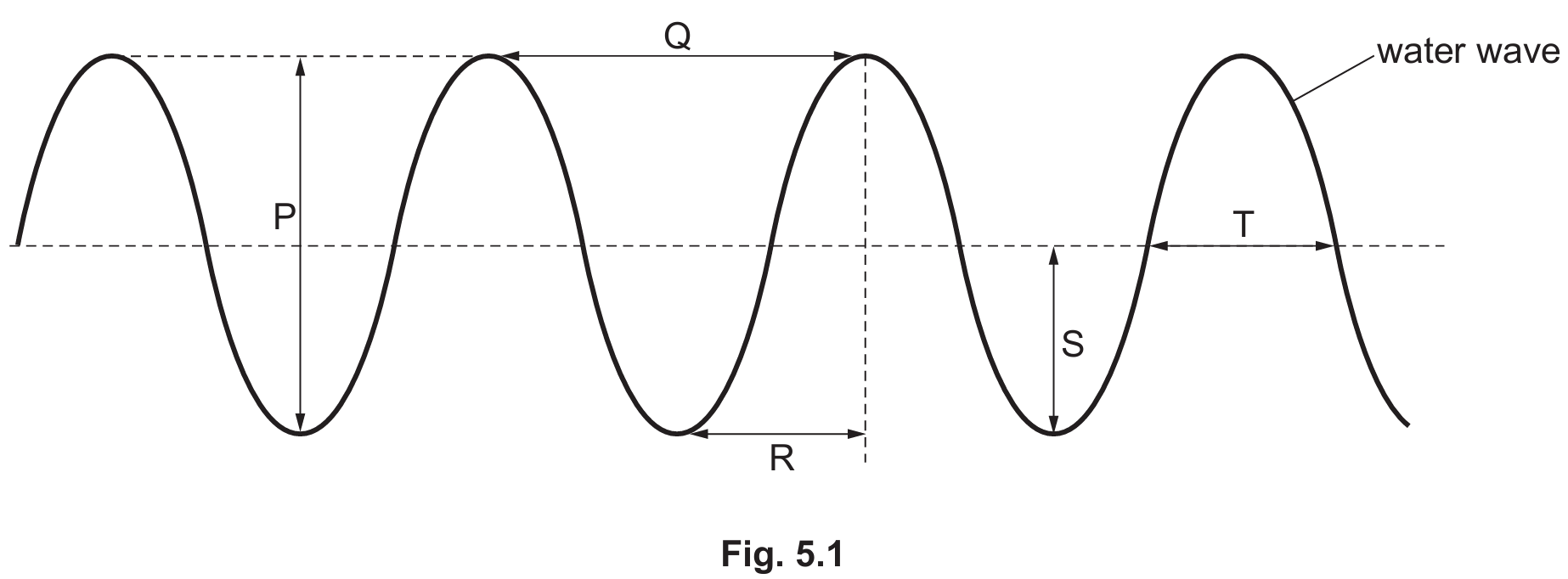
The amplitude of a wave is defined as the maximum displacement of a particle from its equilibrium or rest position. On the wave profile shown in Fig. 5.1, this corresponds to the vertical distance from the central undisturbed line up to the very top of a crest, or equivalently down to the bottom of a trough. The letter S points to exactly this measurement — the height from the midline to the peak of the wave. It is important not to confuse amplitude with the total distance from crest to trough, which would be twice the amplitude. Amplitude is directly related to the energy carried by the wave; a wave with a greater amplitude transports more energy per unit time.
(a)(ii)
For the correct answer:
Q
The wavelength of a wave is the distance of one complete cycle of the wave, measured from any point on the wave to the very next point that is in exactly the same phase — most conveniently from one crest to the next crest, or from one trough to the next trough. In Fig. 5.1, the letter Q spans precisely this distance, marking the length of one full repeating unit of the wave pattern. Wavelength is typically denoted by the Greek letter lambda ($\lambda$) and is measured in metres. It is one of the key properties used to characterise a wave, and together with frequency it determines the wave’s speed through the relationship $v = f\lambda$.
(b)
For the correct answer:
Transverse.
A wave is classified according to the relationship between the direction in which the particles of the medium vibrate and the direction in which the wave energy travels. When water waves move forward, the individual water molecules do not travel along with the wave — instead they oscillate up and down, at right angles (perpendicular) to the direction of wave propagation. Any wave where the particle vibration is perpendicular to the direction of energy transfer is called a transverse wave. Other common examples of transverse waves include all members of the electromagnetic spectrum, such as light, radio waves, and X-rays. This is in contrast to longitudinal waves, such as sound, where particles vibrate parallel to the direction of travel.
(c)
For the correct answer:
The number of complete cycles / vibrations / waves passing a fixed point per unit time (per second).
The frequency of a wave tells us how rapidly the wave is oscillating — specifically, it is the number of complete wave cycles that pass a given fixed point every second. If you were standing at the edge of a pool watching a water wave go by, the frequency would be how many complete crests passed you in one second. Frequency is measured in hertz (Hz), where 1 Hz means one complete cycle per second. It is closely related to the period of the wave, which is the time taken for one complete cycle; the two are reciprocals of each other, expressed as $f = 1/T$. A higher frequency means the wave is oscillating more rapidly and, for electromagnetic waves in a vacuum, corresponds to a shorter wavelength and greater energy.
(d)(i)
For the correct answer:
Gamma rays ($\gamma$-rays) in the far left box; Ultraviolet (UV) in the box between X-rays and visible light.
The electromagnetic spectrum is arranged in order of increasing wavelength (or equivalently, decreasing frequency and energy) from left to right. At the far left end, where the wavelengths are shortest and the energy is greatest, sit gamma rays — the most energetic and penetrating form of electromagnetic radiation, produced by nuclear processes. Moving along the spectrum towards longer wavelengths, we find X-rays, then a gap that should be labelled ultraviolet (UV) radiation, which sits just beyond the violet end of visible light and is responsible for causing sunburn. The remaining regions in order are visible light, infrared, microwaves, and finally radio waves at the longest wavelengths. These two missing labels — gamma rays and ultraviolet — complete the full picture of the electromagnetic spectrum.
(d)(ii)
For the correct answer:
In a vacuum, radio waves travel at the same speed as visible light.
One of the most fundamental properties of the electromagnetic spectrum is that all of its members — regardless of their wavelength or frequency — travel at exactly the same speed in a vacuum. This speed is the speed of light, approximately $3 \times 10^8\text{ m/s}$, often denoted by the letter $c$. Radio waves, despite having very long wavelengths and low frequencies, are still electromagnetic waves and therefore travel at this same universal speed in a vacuum. It is only when electromagnetic waves enter a medium such as glass or water that their speeds differ from one another due to refraction effects. So the correct completion of the sentence is that radio waves travel at the same speed as visible light in a vacuum.
(e)(i)
For the correct answer:
Infrared.
Television remote controls work by emitting pulses of infrared radiation, which is the region of the electromagnetic spectrum with wavelengths just longer than those of visible red light. When a button is pressed on the remote, an infrared LED inside it flashes a coded sequence of infrared pulses towards a sensor on the television set. The sensor detects these pulses and interprets the code to carry out the appropriate function, such as changing the channel or adjusting the volume. Infrared is ideal for this purpose because it is invisible to the human eye, travels in straight lines at the speed of light, and the small distances involved in a living room do not require the high penetrating power or long range of microwaves or radio waves.
(e)(ii)
For the correct answer:
Microwaves.
Satellite television broadcasting uses microwaves to transmit signals between the ground and satellites orbiting the Earth. Microwaves are chosen for this application because their relatively short wavelengths allow them to be directed into narrow, focused beams that can be aimed precisely at a satellite dish, minimising signal loss over the enormous distances involved. Crucially, microwaves are also able to pass through the Earth’s atmosphere — including clouds and rain — with relatively little absorption or scattering, making them reliable for continuous broadcasting under most weather conditions. The satellite receives the uplinked microwave signal from a ground station, amplifies it, and retransmits it back down to receiving dishes on the ground across a wide geographic area.
Question 6
Most-appropriate topic codes (Cambridge IGCSE Physics 0625):
• Topic $3.2$ — Light
▶️ Answer/Explanation
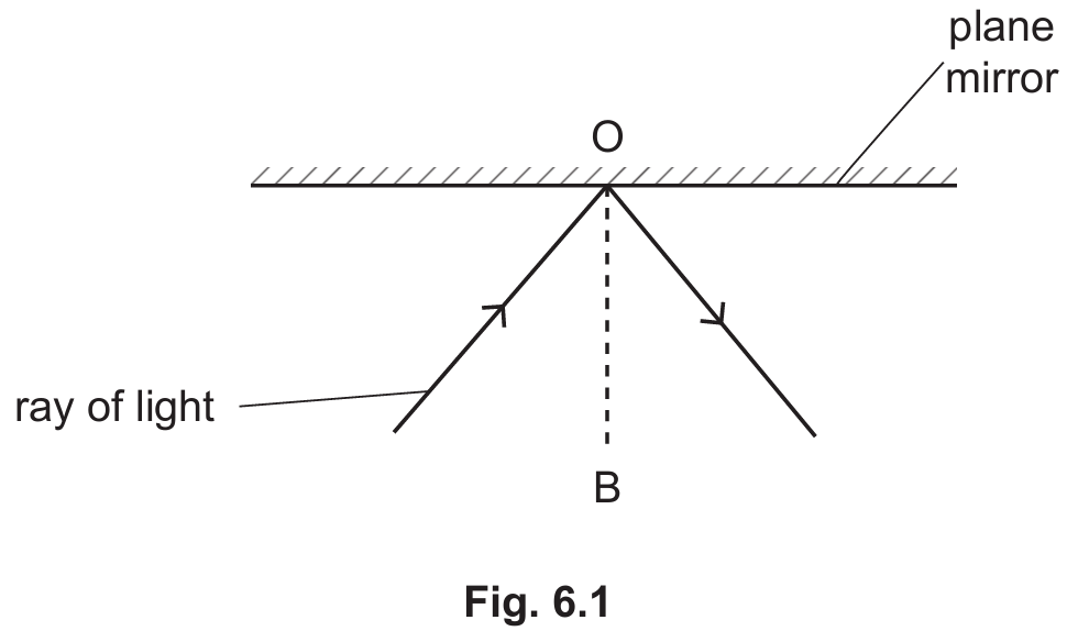
(a)(i)
For the correct answer:
Normal (line).
The dashed line OB drawn perpendicularly to the surface of the plane mirror at the exact point where the incoming ray of light strikes it is called the normal. It is always constructed at $90^{\circ}$ to the reflecting surface at the point of incidence, and it serves as the essential reference line from which both the angle of incidence and the angle of reflection are measured. Without the normal, it would be impossible to apply the law of reflection consistently, because angles measured from the mirror surface itself would give different values depending on the orientation of the mirror. The normal is a purely imaginary construction — it has no physical existence — but it is a fundamental tool in all ray diagrams involving reflection and refraction.
(a)(ii)
For the correct answer:
An X drawn in the angle between the dashed normal line OB and the reflected ray (on the opposite side of the normal from the incident ray).
The angle of reflection is always measured between the normal line and the reflected ray, not between the reflected ray and the mirror surface itself. In Fig. 6.1, the reflected ray leaves the mirror surface on the opposite side of the normal OB from the incoming incident ray. To correctly indicate the angle of reflection, the letter X (or an arc) must be placed in the gap between the normal line OB and the outgoing reflected ray, on the right-hand side of OB. Placing the X anywhere else — for example between the reflected ray and the mirror surface — would be measuring the wrong angle and would not represent the angle of reflection as defined in optics.
(a)(iii)
For the correct answer:
The angle of incidence is equal to the angle of reflection.
The law of reflection is one of the most fundamental and universally applicable laws in optics. It states that when a ray of light strikes a smooth, flat reflecting surface, the angle at which it arrives — measured between the incoming ray and the normal at the point of incidence — is always exactly equal to the angle at which it leaves, measured between the reflected ray and the same normal. Both angles are measured on the same side of the reflecting surface, and the incident ray, the normal, and the reflected ray all lie in the same plane. This law holds true for all smooth reflective surfaces, regardless of the wavelength or colour of the light involved, and it applies equally whether the surface is a plane mirror, a curved mirror, or any other polished reflector.
(b)
For the correct answer:
Same size and Upright.
When a candle is placed in front of a plane mirror, the image it produces has several well-defined characteristics that can be determined from the geometry of reflection. The image is the same size as the object — the mirror neither magnifies nor shrinks it — because the angle of incidence equals the angle of reflection for every ray, preserving the proportions of the object exactly. The image is also upright, meaning it appears the right way up and is not inverted vertically, unlike the images formed by converging lenses beyond their focal point. Additionally, the image is virtual (it cannot be projected onto a screen), located as far behind the mirror as the object is in front, and laterally inverted (left and right are swapped), though none of these options appeared in the given list.
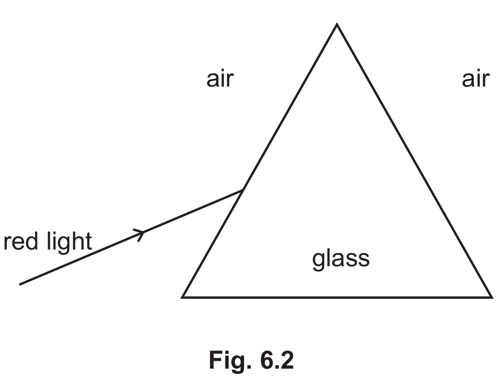
(c)(i)
For the correct answer:
A ray drawn bending towards the normal as it enters the glass prism, travelling straight through the glass, then bending away from the normal as it exits into the air on the other side.
When drawing the path of the red light through the prism, the ray must be shown changing direction at both surfaces where it crosses a boundary between two different optical media. At the first surface where air meets glass, the ray bends towards the normal because it is entering an optically denser medium where its speed decreases. It then travels in a straight line through the uniform glass of the prism. At the second surface where the glass meets air again, the ray bends away from the normal because it is now entering a less dense medium where its speed increases once more. The overall effect is that the ray emerges from the prism travelling in a different direction from which it originally entered, shifted by the combined refractions at both surfaces.
(c)(ii)
For the correct answer:
The red light refracts (changes direction) at each boundary due to a change in its speed as it moves between media of different optical densities.
The reason the red light follows this bent path is the phenomenon of refraction, which occurs whenever a wave crosses a boundary between two media in which it travels at different speeds. When the light ray passes from air into the optically denser glass, its speed decreases because the glass molecules interact more strongly with the light, slowing it down. This reduction in speed causes the ray to bend towards the normal at the first surface. When the ray then exits the glass back into the less dense air at the second surface, its speed increases again, and it bends away from the normal accordingly. The amount of bending at each surface depends on the angle of incidence and the refractive index of the glass, which describes how much slower light travels in glass compared to air or a vacuum.
Question 7
Most-appropriate topic codes (Cambridge IGCSE Physics 0625):
• Topic $4.1$ — Simple phenomena of magnetism
▶️ Answer/Explanation
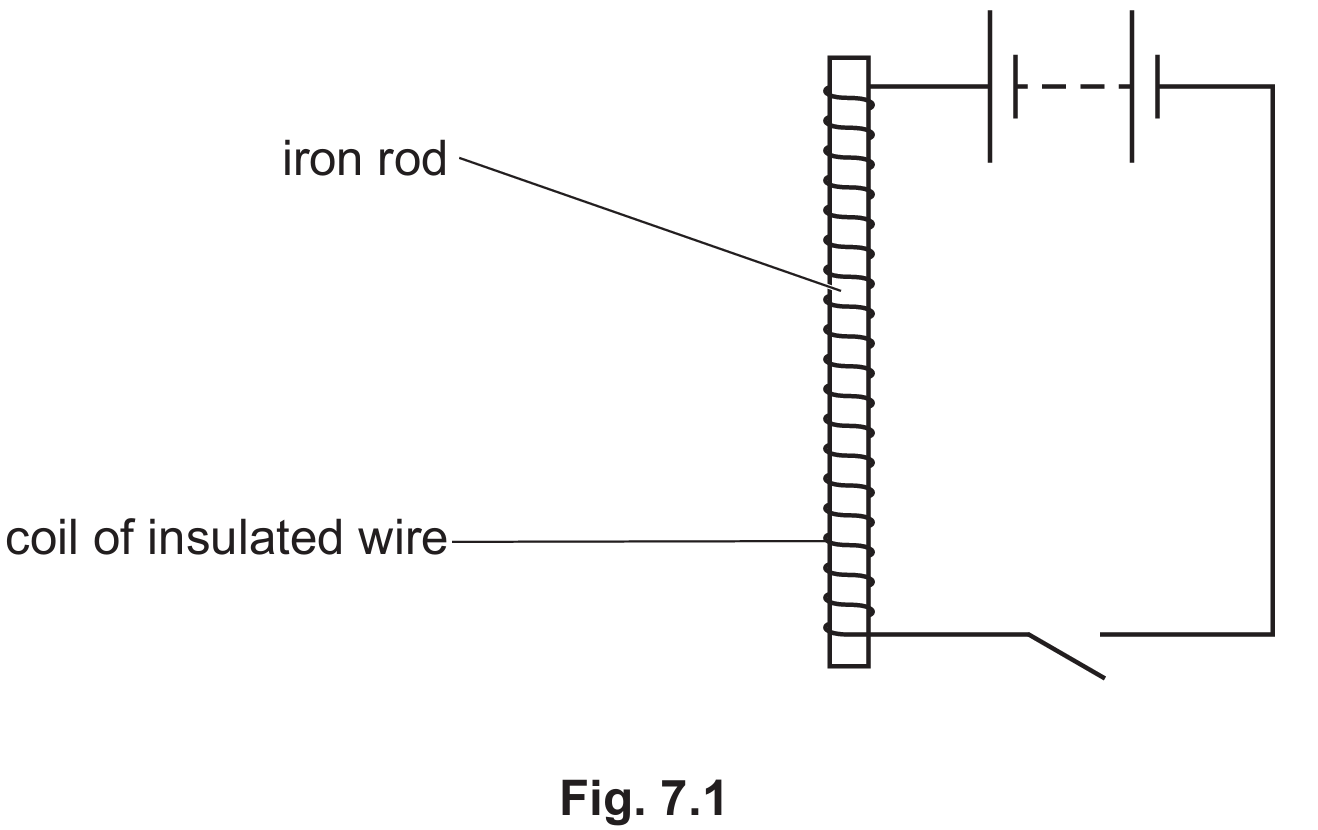
(a)(i)
For the correct answer:
Electromagnet.
The device shown in Fig. 7.1 is an electromagnet. It is constructed by winding a coil of insulated conducting wire — known as a solenoid — around a soft iron core and then passing an electric current through the wire. The flowing current generates a magnetic field around each turn of wire, and because all the turns are wound in the same direction, their individual magnetic fields combine and reinforce each other to produce a strong, unified magnetic field along the axis of the coil. The soft iron core becomes magnetised within this field and greatly amplifies the overall magnetic strength of the device. The result is a powerful magnet whose properties are directly controlled by the electric current supplied to it.
(a)(ii)
For the correct answer:
It can be switched on and off / its strength can be easily controlled.
The most significant practical advantage of an electromagnet over a permanent magnet is that it can be turned on and off simply by opening or closing the electrical circuit that supplies the current. When the current flows, the magnetic field exists and the electromagnet attracts magnetic materials; when the current is cut off, the magnetic field disappears almost instantly and the soft iron core loses its magnetism. This switchable nature makes it far more versatile than a permanent magnet, which maintains its field continuously and cannot be deactivated. Furthermore, the strength of the electromagnet can be precisely adjusted at any time by changing the magnitude of the current, giving the user complete control over its magnetic force — something that is impossible with an ordinary permanent magnet.
(a)(iii)
For the correct answer:
1. Increase the current through the coil (or increase the supply voltage).
2. Increase the number of turns of wire wound around the core.
The strength of an electromagnet depends on the intensity of the magnetic field produced by the current-carrying coil, and there are two straightforward ways to increase this. First, increasing the electric current flowing through the wire — by raising the supply voltage, for example — directly increases the magnetic field strength around each individual turn of the coil, resulting in a stronger overall magnet. Second, winding more turns of wire around the iron core means that more loops contribute their magnetic fields in the same direction, so the fields add together more effectively to produce a larger combined field. Both methods increase what physicists call the magnetomotive force acting on the core, driving it to a higher level of magnetisation and producing a noticeably stronger electromagnet.
(a)(iv)
For the correct answer:
Scrapyard crane / electric bell / relay / MRI scanner / loudspeaker.
One very common and practical use of an electromagnet is in a scrapyard crane. In this application, a large, powerful electromagnet is suspended from a crane and switched on to attract and lift heavy masses of scrap iron or steel, which can then be moved to a desired location. Once positioned correctly, the operator simply switches off the current, causing the electromagnet to instantly lose its magnetism and release the metal, dropping it exactly where needed. This would be completely impossible with a permanent magnet, since there would be no way to release the attracted metal. The ability to switch the magnetic force on and off on demand is what makes the electromagnet uniquely suited to this kind of lifting and sorting task.
(b)(i)
For the correct answer:
Steel becomes permanently magnetised and retains its magnetism after the current is switched off, unlike soft iron which loses its magnetism immediately.
Soft iron is used as the core material in an electromagnet because it is magnetically soft — meaning it is very easy to magnetise when a current flows, but it loses virtually all of its magnetism the moment the current is switched off. Steel, by contrast, is a magnetically hard material. If a steel rod were used as the core instead, it would become magnetised when the current flows, but it would retain a significant amount of that magnetism even after the current is turned off, becoming a permanent magnet. This is a major disadvantage for an electromagnet, because the device would no longer switch off cleanly — it would continue to attract magnetic materials even when the circuit is open, making it unsuitable for applications that rely on the magnetism being fully controllable and temporary.
(b)(ii)
For the correct answer:
The electromagnet would not work effectively / it would produce a much weaker magnetic field, because copper is a non-magnetic material.
Copper is a non-magnetic material, meaning it cannot be magnetised and does not respond to magnetic fields in the way that iron or steel does. If a copper rod were placed inside the coil in place of the soft iron core, it would not become magnetised when the current flows through the surrounding wire. The coil of wire would still produce a small magnetic field due to the current alone, but without the iron core to concentrate and greatly amplify this field, the overall magnetic strength of the device would be drastically reduced and largely ineffective for practical purposes. The role of the soft iron core is to provide a high-permeability pathway for the magnetic field lines, multiplying the field strength many times over — a function that copper, being non-magnetic, is completely unable to perform.
Question 8
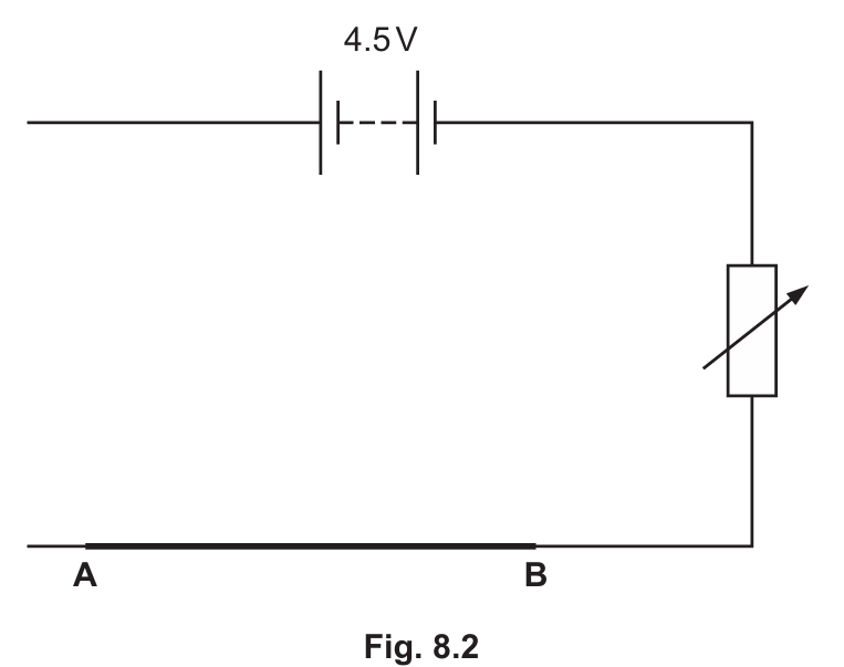
Most-appropriate topic codes (Cambridge IGCSE Physics 0625):
• Topic $4.2$ — Electrical quantities
• Topic $4.3$ — Electric circuits
▶️ Answer/Explanation
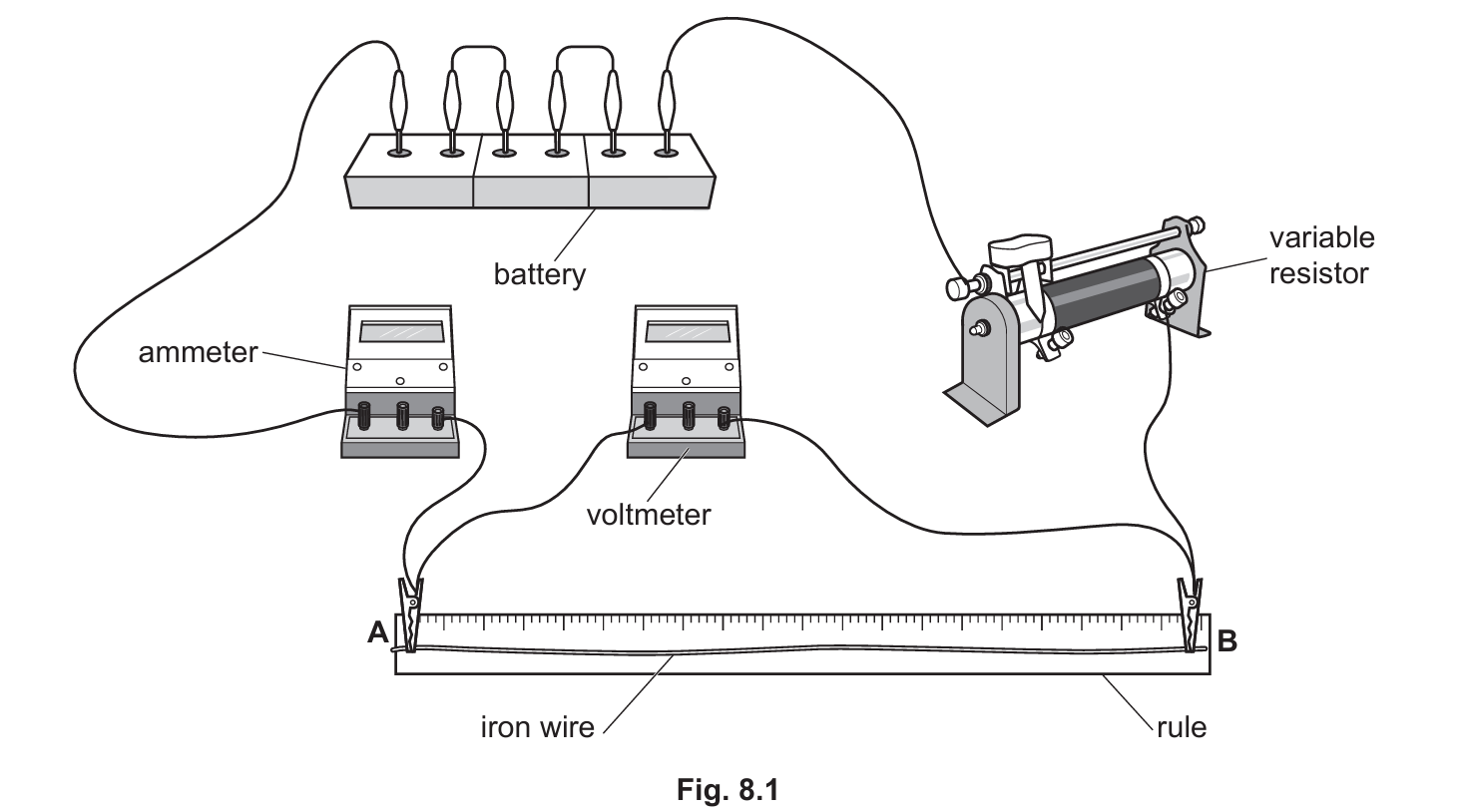
(a)
For the correct answer:
Ammeter, battery, and iron wire AB drawn in a complete series loop; voltmeter connected in parallel directly across points A and B; correct standard circuit symbols used throughout.
When converting the physical arrangement in Fig. 8.1 into a formal circuit diagram, the key is to correctly identify which components are in series and which are in parallel. The battery (cell), the ammeter, and the iron wire between points A and B all form a single continuous conducting loop — they are connected in series, meaning the same current flows through each of them in turn. The ammeter must be drawn in series because it measures the current flowing through the wire, and any instrument measuring current must be placed directly in the main circuit path. The voltmeter, however, must be drawn separately, connected in parallel across the two endpoints A and B of the iron wire only, because it measures the potential difference specifically across that component. Standard circuit symbols — a circle with the letter A for the ammeter and a circle with the letter V for the voltmeter — must be used throughout to produce a correctly drawn and recognised circuit diagram.
(b)
For the correct answer:
$R = 14\ \Omega$
To calculate the resistance of the iron wire, we apply Ohm’s Law, which states that the resistance of a conductor is equal to the potential difference across it divided by the current flowing through it, expressed as $R = V / I$. Substituting the values read from the meters: $R = 1.56\text{ V} \div 0.112\text{ A} = 13.928\ldots\ \Omega$, which rounds to $14\ \Omega$ to two significant figures. It is essential to include the correct unit for resistance in the final answer — the ohm, represented by the Greek letter omega ($\Omega$) — as the question explicitly requires it and omitting it would lose a mark. This experiment is a standard method for determining resistance: by measuring the voltage across a component and the current through it simultaneously, Ohm’s Law allows the resistance to be calculated accurately without needing to know anything about the material or dimensions of the wire directly.
Question 9
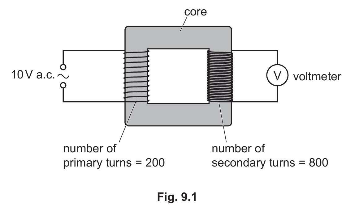
Most-appropriate topic codes (Cambridge IGCSE Physics 0625):
• Topic $4.5.6$ — Transformers
▶️ Answer/Explanation
(a)
For the correct answer:
Alternating current.
The abbreviation a.c. stands for alternating current. Unlike direct current (d.c.), where electrons flow continuously in one fixed direction around a circuit, alternating current is a type of electric current in which the direction of electron flow reverses repeatedly and periodically. In most countries, mains electricity alternates at a frequency of 50 Hz or 60 Hz, meaning the current changes direction 50 or 60 times every second respectively. This constantly reversing nature of a.c. is not merely a technical detail — it is absolutely fundamental to how transformers operate, as the changing current is what produces the continuously varying magnetic field that makes electromagnetic induction in the secondary coil possible.
(b)
For the correct answer:
Step-up transformer.
The transformer shown in Fig. 9.1 is a step-up transformer. This classification is determined by comparing the number of turns on the primary coil (the input side, connected to the power supply) with the number of turns on the secondary coil (the output side, connected to the voltmeter). From the diagram, the primary coil has 200 turns while the secondary coil has 800 turns — the secondary has more turns than the primary. Whenever the secondary coil has more turns than the primary, the output voltage is greater than the input voltage, meaning the transformer steps the voltage up. This is in contrast to a step-down transformer, where the secondary has fewer turns than the primary and the output voltage is lower than the input.
(c)
For the correct answer:
Soft iron.
The core of a transformer must be made from a material that is highly magnetically permeable — meaning it can concentrate and channel magnetic field lines very efficiently — and that can also magnetise and demagnetise rapidly and completely as the alternating current causes the magnetic field to reverse direction many times per second. Soft iron satisfies both of these requirements exceptionally well. It has a very high magnetic permeability, allowing it to carry the changing magnetic flux from the primary coil to the secondary coil with minimal loss, and it is magnetically soft, meaning it does not retain significant residual magnetism when the field changes direction. Steel, by contrast, would be unsuitable because its magnetically hard nature means it lags behind the rapidly changing field, wasting energy as heat.
(d)
For the correct answer:
$40\text{ V}$
Calculation: $\dfrac{V_s}{V_p} = \dfrac{N_s}{N_p} \Rightarrow V_s = \dfrac{N_s}{N_p} \times V_p = \dfrac{800}{200} \times 10 = 40\text{ V}$
To calculate the output voltage of the transformer, we apply the standard transformer equation, which states that the ratio of the secondary voltage to the primary voltage is equal to the ratio of the number of turns on the secondary coil to the number of turns on the primary coil: $V_s / V_p = N_s / N_p$. Rearranging to find the secondary (output) voltage gives $V_s = (N_s / N_p) \times V_p$. Substituting the values from Fig. 9.1 — a primary coil of 200 turns, a secondary coil of 800 turns, and an input voltage of $10\text{ V}$ — we get $V_s = (800 / 200) \times 10 = 4 \times 10 = 40\text{ V}$. The turns ratio is 4, so the voltage is multiplied by the same factor of 4, giving a voltmeter reading of $40\text{ V}$.
(e)
For the correct answer:
Zero / $0\text{ V}$.
If the a.c. power supply is replaced by a $10\text{ V}$ d.c. battery, the voltmeter reading drops to zero. This is because a transformer operates entirely on the principle of electromagnetic induction — a voltage is induced in the secondary coil only when the magnetic flux passing through the core is continuously changing. With an alternating current in the primary coil, the magnetic field in the core reverses direction rapidly, producing a constantly changing flux that cuts through the turns of the secondary coil and induces an alternating voltage in it. A steady d.c. supply, however, produces a constant, unchanging current in the primary coil, which in turn creates a magnetic field that is fixed and does not change with time. Since there is no change in magnetic flux, there is no electromagnetic induction in the secondary coil, and consequently no voltage is induced — the voltmeter reads exactly $0\text{ V}$.
Question 10
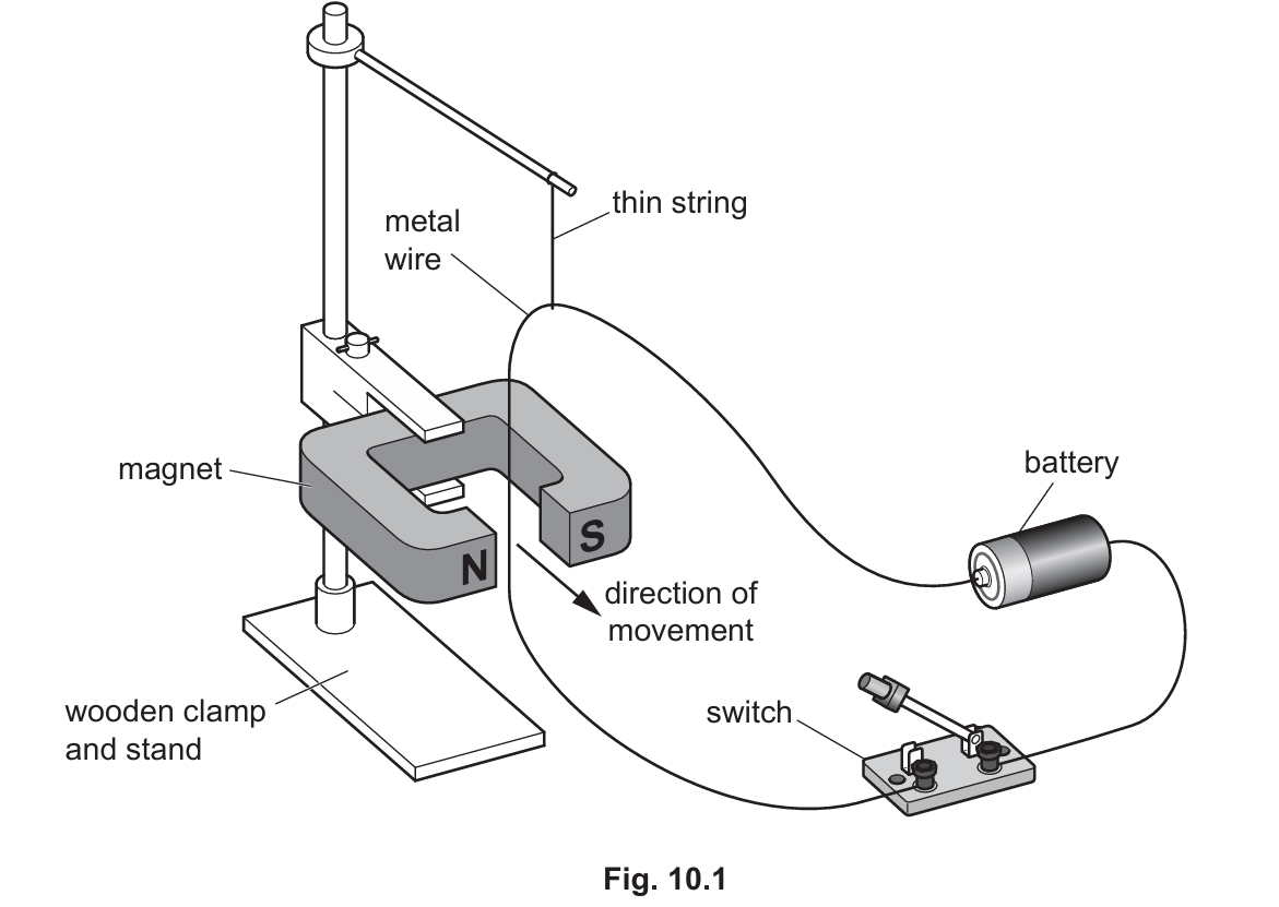
Most-appropriate topic codes (Cambridge IGCSE Physics 0625):
• Topic $4.5.3$ — Magnetic force of a current
▶️ Answer/Explanation
(a)(i)
For the correct answer:
1. Increase the current through the wire (by increasing the voltage of the cell). 2. Use a stronger magnet.
The force experienced by a current-carrying conductor placed in a magnetic field — known as the motor effect — depends on two key factors: the magnitude of the current flowing through the wire and the strength of the magnetic field in which it sits. Increasing either of these will directly increase the force on the wire, causing it to deflect more strongly. To increase the current, one could increase the voltage of the battery or cell in the circuit, since a higher voltage drives more current through the wire according to Ohm’s Law. Alternatively, replacing the existing magnet with a stronger one intensifies the magnetic field in the gap, which interacts more powerfully with the current in the wire and produces a greater force. Both changes independently increase the motor effect force, and applying both simultaneously would produce an even more dramatic increase.
(a)(ii)
For the correct answer:
Reverse the direction of the current (by reversing the battery connections) OR reverse the direction of the magnetic field (by swapping the poles of the magnet).
The direction of the force on a current-carrying wire in a magnetic field is determined by the relative directions of both the current and the magnetic field, as described by Fleming’s left-hand rule. If either one of these two directions is reversed while the other remains the same, the resulting force will act in the opposite direction, causing the wire to move the other way. In practice, the simplest way to reverse the current direction is to disconnect the battery and reconnect it the other way around in the circuit, so that conventional current flows through the wire in the opposite direction. Alternatively, physically turning the magnet around so that the north and south poles swap positions reverses the direction of the magnetic field in the gap, which equally results in the force on the wire reversing. Reversing both simultaneously would cancel out and the wire would move in the original direction again.
(b)
For the correct answer:
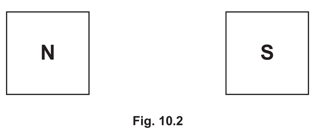
Three or more straight, parallel, evenly spaced horizontal lines drawn across the gap between the poles, with arrows on each line pointing from the North pole (N) to the South pole (S).
The magnetic field between two flat, opposing magnetic poles — one north and one south facing each other directly — is uniform. A uniform field is represented in a diagram by drawing field lines that are perfectly straight, parallel to one another, and evenly spaced throughout the gap, indicating that the field has the same strength and direction at every point between the poles. This is in contrast to the curved, spreading field lines seen around the outside of a bar magnet. By convention, magnetic field lines always point from north to south — that is, they leave the north pole and enter the south pole — so the arrows on every line drawn in the gap must point from the N pole towards the S pole. At least three lines should be drawn to clearly convey the uniform nature of the field.
Question 11
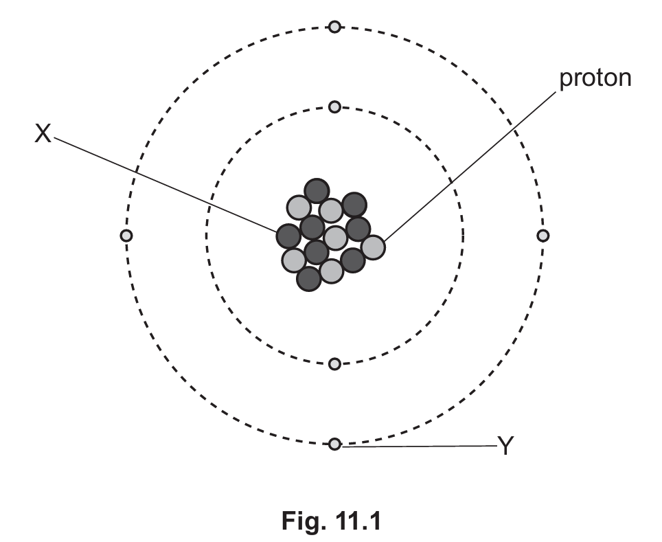
Most-appropriate topic codes (Cambridge IGCSE Physics 0625):
• Topic $5.1.1$ — Atomic model
• Topic $5.2$ — Radioactivity
▶️ Answer/Explanation
(a)(i)
For the correct answer:
Neutron.
In the diagram of the carbon-14 atom in Fig. 11.1, particle X is located inside the central nucleus alongside the protons. The nucleus of any atom contains only two types of particles — protons and neutrons — and since the protons are already identified separately, particle X must be a neutron. Neutrons are electrically neutral particles, meaning they carry no charge, and they have a relative mass of approximately 1 atomic mass unit, which is very similar to the mass of a proton. Their presence in the nucleus is essential for binding the nucleus together and contributing to the overall mass of the atom, but they do not affect the chemical identity of the element, which is determined solely by the number of protons.
(a)(ii)
For the correct answer:
Electron.
Particle Y in Fig. 11.1 is shown orbiting the nucleus in the shells or energy levels that surround it — this is the characteristic position of an electron within the atomic model. Electrons are negatively charged particles with a negligibly small mass compared to protons and neutrons (approximately 1/1836 of a proton’s mass), which is why they are considered to contribute virtually nothing to the overall mass of the atom. In a neutral atom, the number of electrons orbiting the nucleus is exactly equal to the number of protons in the nucleus, balancing the positive charge of the protons with an equal amount of negative charge. Carbon has 6 protons and therefore 6 electrons in its neutral state.
(a)(iii)
For the correct answer:
14.
The nucleon number, also called the mass number, is defined as the total number of nucleons — that is, the combined count of protons and neutrons — present in the nucleus of an atom. The name “carbon-14” directly encodes this information: the number 14 is the nucleon number of this particular isotope of carbon. Carbon always has 6 protons (which defines it as carbon), so the number of neutrons in carbon-14 can be deduced by subtracting the proton number from the nucleon number: $14 – 6 = 8$ neutrons. The nucleon number is the superscript written to the upper left of the chemical symbol in standard nuclear notation, and for carbon-14 it is simply and directly 14.
(b)
For the correct answer:
A beta-particle is a fast-moving electron emitted from the nucleus.
When a nucleus undergoes beta decay, a neutron within the nucleus spontaneously transforms into a proton, and in doing so it ejects a high-speed, high-energy electron from the nucleus itself — this ejected electron is the beta-particle. It is important to understand that this electron does not come from the electron shells surrounding the nucleus; it is created and emitted directly from within the nucleus during the decay process. As a result of beta decay, the nucleon number of the atom remains unchanged (since a neutron is converted to a proton, the total count stays the same), but the proton number increases by one, effectively changing the element into the next one up in the periodic table. Beta-particles carry a charge of $-1$ and have a very small mass.
(c)
For the correct answer:
$17\,400\text{ years}$
Calculation: $16\,000 \rightarrow 8\,000 \rightarrow 4\,000 \rightarrow 2\,000$ (3 half-lives). Age $= 3 \times 5800 = 17\,400\text{ years}$.
To find the age of the spoon, we need to determine how many half-lives have elapsed since the spoon was made, by working out how many times the original number of carbon-14 atoms has halved to reach its current value. Starting from the original count of $16\,000$ atoms: after one half-life it becomes $8\,000$; after a second half-life it becomes $4\,000$; and after a third half-life it becomes $2\,000$, which matches the present-day count exactly. This tells us that exactly 3 half-lives have passed since the tree was cut down to make the spoon. Since each half-life of carbon-14 lasts $5\,800$ years, the total age of the spoon is $3 \times 5\,800 = 17\,400\text{ years}$. This technique of using the predictable decay of carbon-14 to date organic materials is known as radiocarbon dating.