AP Physics 1- 5.4 Rotational Inertia - Exam Style questions - FRQs- New Syllabus
Rotational Inertia AP Physics 1 FRQ
Unit 5: Torque and Rotational Dynamics
Weightage : 10-15%
Question
| \( \theta \) \( (\mathrm{degrees}) \) | \( F_T \) \( (\mathrm{N}) \) |
|---|---|
| \( 22 \) | \( 21 \) |
| \( 31 \) | \( 17 \) |
| \( 36 \) | \( 13 \) |
| \( 45 \) | \( 12 \) |
| \( 80 \) | \( 8 \) |
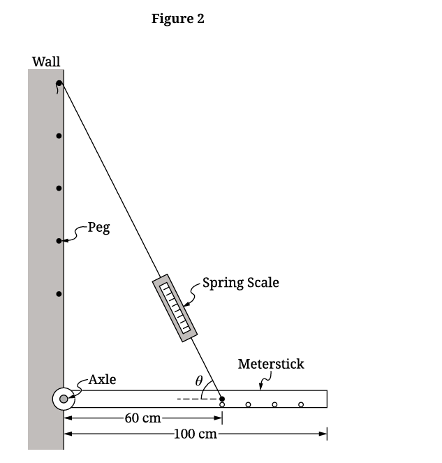
\( F_T = \dfrac{5Mg}{6\sin\theta} \)
Vertical axis: _____ Horizontal axis: \( \dfrac{1}{\sin\theta} \)
• Clearly label the vertical axis, including units as appropriate.
• Plot the points you recorded in Table \( 2 \).
Most-appropriate topic codes (AP Physics 1):
• Topic \( 5.5 \) — Rotational Equilibrium and Newton’s First Law in Rotational Form (Part \( \mathrm{A} \), Part \( \mathrm{B} \), Part \( \mathrm{C} \), Part \( \mathrm{D} \))
• Topic \( 2.2 \) — Forces and Free-Body Diagrams (Part \( \mathrm{A} \), Part \( \mathrm{C} \))
• Topic \( 1.1 \) — Scalars and Vectors in One Dimension (Part \( \mathrm{C} \), graphing and measured quantities)
▶️ Answer/Explanation
A
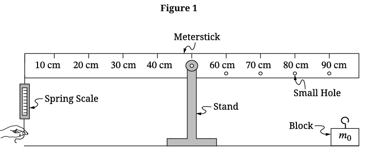
Attach the block of unknown mass \( m_0 \) to one of the small holes in the meterstick. Keep the meterstick horizontal and record the force reading from the spring scale.
Repeat the measurement for several different block positions \( r_b \) measured from the stand \( (\text{pivot}) \). For each position, also record the distance from the stand to the spring scale attachment point, which stays fixed.
To reduce experimental uncertainty, repeat the spring-scale reading multiple times for each block position and average the values. It also helps to use many different hole positions so the graph is based on several data points instead of only one or two.
A good experimental habit is to make sure the meterstick is level before reading the scale each time and to read the scale at eye level to reduce parallax error.
B
One valid graph is force as a function of the distance from the stand to the block.
Taking torques about the stand,
\( F_s r_s = m_0 g\, r_b \)
where \( F_s \) is the spring-scale force, \( r_s \) is the distance from the stand to the spring scale, and \( r_b \) is the distance from the stand to the block.
Rearranging,
\( F_s = \left(\dfrac{m_0 g}{r_s}\right) r_b \)
So a graph of \( F_s \) on the vertical axis versus \( r_b \) on the horizontal axis is linear. Its slope is
\( \text{slope} = \dfrac{m_0 g}{r_s} \)
Therefore,
\( m_0 = \dfrac{(\text{slope})\,r_s}{g} \)
Any equivalent linear graph that correctly relates force and distance also earns full credit.
C(i)
Vertical axis: \( F_T \)
Since \( F_T = \dfrac{5Mg}{6\sin\theta} = \left(\dfrac{5Mg}{6}\right)\left(\dfrac{1}{\sin\theta}\right) \), a plot of \( F_T \) versus \( \dfrac{1}{\sin\theta} \) is linear.
C(ii)
Use the calculated values of \( \dfrac{1}{\sin\theta} \) together with the measured values of \( F_T \).
| Table \( 2 \) | \( \theta \) \( (\mathrm{degrees}) \) | \( \dfrac{1}{\sin\theta} \) | \( F_T \) \( (\mathrm{N}) \) |
|---|---|---|---|
| Point \( 1 \) | \( 22 \) | \( 2.67 \) | \( 21 \) |
| Point \( 2 \) | \( 31 \) | \( 1.94 \) | \( 17 \) |
| Point \( 3 \) | \( 36 \) | \( 1.70 \) | \( 13 \) |
| Point \( 4 \) | \( 45 \) | \( 1.41 \) | \( 12 \) |
| Point \( 5 \) | \( 80 \) | \( 1.02 \) | \( 8 \) |
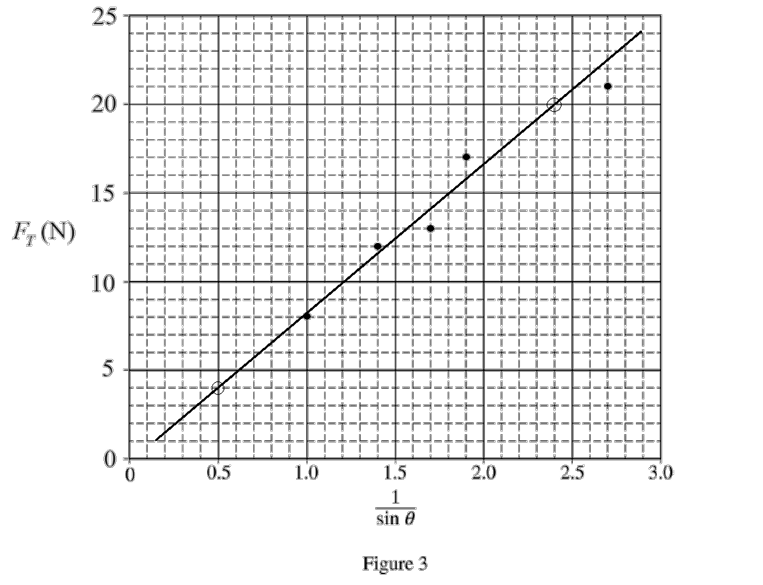
The graph should have vertical axis \( F_T\ (\mathrm{N}) \) and horizontal axis \( \dfrac{1}{\sin\theta} \). Plot the points:
\( (2.67,21),\ (1.94,17),\ (1.70,13),\ (1.41,12),\ (1.02,8) \)
These points lie approximately on a straight line.
C(iii)
Draw a straight best-fit line through the plotted data. It should have positive slope and pass close to the origin.
Because the equation has the form \( F_T = \left(\dfrac{5Mg}{6}\right)\left(\dfrac{1}{\sin\theta}\right) \), the slope of the best-fit line is the important quantity for finding \( M \).
D
From a reasonable best-fit line, the slope is about \( 8.4\ \mathrm{N} \).
Since
\( F_T = \left(\dfrac{5Mg}{6}\right)\left(\dfrac{1}{\sin\theta}\right) \),
the slope is \( \dfrac{5Mg}{6} \).
Therefore,
\( M = \dfrac{6(\text{slope})}{5g} \)
\( M = \dfrac{6(8.4\ \mathrm{N})}{5(9.8\ \mathrm{N/kg})} \)
\( M \approx 1.03\ \mathrm{kg} \)
So an experimental value for the mass of the meterstick is \( \boxed{1.0\ \mathrm{kg}} \) \( (\text{approximately}) \).