Behavior of a Circuit
Components of a Circuit: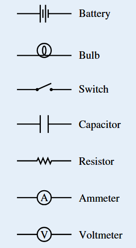
A circuit is composed of one or more electrical loops. These loops may contain various circuit elements:
- Conducting Wires: Provide a pathway for charge to move.
- Battery (Source of emf): Provides an electric potential difference that drives current.
- Resistor: Opposes the flow of current, converting electrical energy into heat.
- Lightbulb: A resistor designed to emit light when current passes through it.
- Capacitor: Stores electrical energy in the form of separated charges.
- Switch: Opens or closes the circuit, controlling whether current flows.
- Ammeter: Measures the current through a circuit element (connected in series).
- Voltmeter: Measures the potential difference across a circuit element (connected in parallel).
Closed Electrical Loop:
A closed loop is a continuous conducting path in which charges can circulate. For current to exist, at least one closed loop must be present, including a source of emf and a conducting path.
Types of Circuits:
- Closed Circuit: A circuit in which charges are able to flow. Example: a battery connected to a resistor with a closed switch.
- Open Circuit: A circuit in which the path is broken (e.g., a switch is open), so charges cannot flow.
- Short Circuit: A circuit where charges flow through a path of very low resistance, bypassing other circuit elements. In this case, there is no significant change in potential difference across the shorted path. This can lead to dangerously high currents.
Multiple Loops:
A single circuit element (e.g., a resistor) may belong to multiple loops in a circuit. This is common in parallel circuits, where current divides among different branches and recombines.
Circuit Schematics:
Circuit schematics are simplified diagrams that use symbols for batteries, resistors, capacitors, switches, and meters to represent the physical circuit. These schematics help analyze circuit behavior using principles such as Ohm’s law and Kirchhoff’s rules.
Circuit Properties:
The overall properties of a circuit (such as total resistance, current distribution, and energy dissipation) depend not only on the values of the individual elements but also on their arrangement (series vs. parallel connections, presence of multiple loops, etc.).
Example :
Distinguish between an open circuit, a closed circuit, and a short circuit, and explain the expected current and potential-difference behavior in each case.
▶️ Answer/Explanation
Open circuit:
Path is broken (e.g., switch open) so charges cannot flow around the loop.
- Current: \( \text{I}=0 \) (no steady current through the broken loop).
- Potential difference: The source (battery) still provides a potential difference across its terminals, but no charge flows; voltmeters across elements may read nonzero values while ammeters read zero.
- Physical reasoning: There is no closed path for charges to move, so microscopic thermal motion may continue but net charge transport is zero.
Closed circuit (normal operation):
Complete conducting path including a source of emf and circuit elements (switch closed).
- Current: Nonzero steady current determined by the circuit arrangement and element values (e.g., Ohm’s law for a single loop: \( \text{V}=\text{IR} \)).
- Potential difference: Voltage drops across circuit elements sum to the emf(s) in each loop (Kirchhoff’s loop rule).
- Physical reasoning: Charges move around the loop driven by emf, energy supplied by the source is converted in resistors, bulbs, etc.
Short circuit:
A low-resistance path bypasses other elements so charges preferentially flow through the short.
- Current: Very large current flows through the short path (limited only by internal resistance and wiring), potentially dangerous.
- Potential difference: The potential difference across the shorted segment is (approximately) zero — elements bypassed by the short see little or no voltage and thus little current through them.
- Physical reasoning: Charges choose the path of least resistance; because the short has negligible drop, the source must supply large current, causing heating or damage.