Image Formed by a Mirror
Mirrors form images by the reflection of light. The characteristics of the image depend on the type of mirror (plane, concave, or convex) and the position of the object.
Plane Mirror:
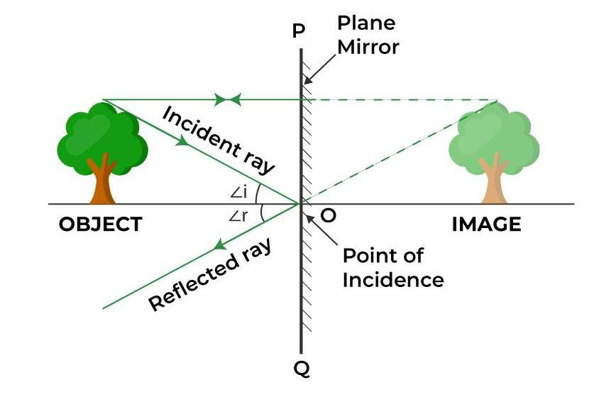
Forms a virtual image (cannot be projected on a screen).
- The image is upright and of the same size as the object.

- The image is formed at the same distance behind the mirror as the object is in front of it.
- The image is laterally inverted (left-right reversed).
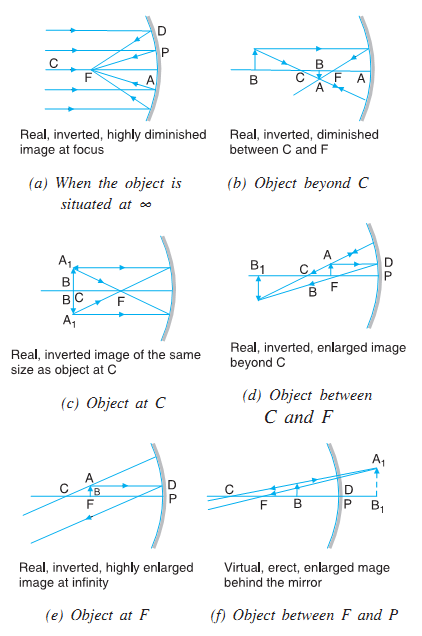
Concave Mirror:
The image characteristics depend on the object’s distance from the mirror:
- Object at infinity: Image is real, inverted, and formed at the focus (highly diminished).
- Object beyond center of curvature (C): Image is real, inverted, diminished, and formed between focus (F) and center (C).
- Object at center of curvature (C): Image is real, inverted, same size, and formed at C.
- Object between C and F: Image is real, inverted, magnified, and formed beyond C.
- Object at focus (F): Image is formed at infinity.
- Object between F and pole (P): Image is virtual, upright, magnified, and formed behind the mirror.
Convex Mirror:
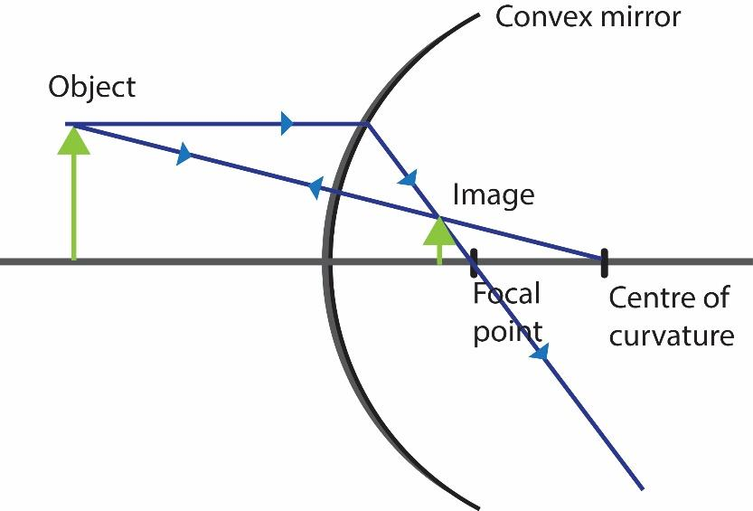
Always forms a virtual, upright, and diminished image.
- The image is formed behind the mirror between the pole (P) and the focus (F).
- Used in rearview mirrors because they provide a wide field of view.
Example :
An object is placed between the focus and pole of a concave mirror. Describe the image formed.
▶️ Answer/Explanation
The image is virtual, upright, and magnified, and it appears behind the mirror. This is why concave mirrors are often used as shaving or makeup mirrors.
Mirror Formula
The location of an image formed by a spherical mirror depends on the focal length of the mirror and the distance between the object and the mirror surface. This relationship is given by the mirror equation:
\(\mathrm{\dfrac{1}{f} = \dfrac{1}{v} + \dfrac{1}{u}}\)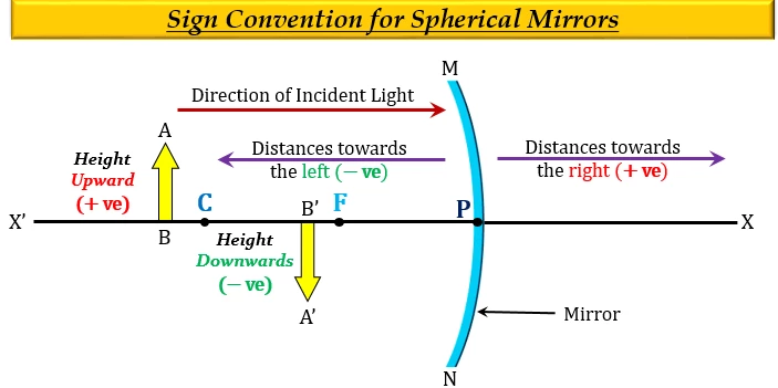
- \(\mathrm{f}\) = focal length of the mirror
- \(\mathrm{u}\) = object distance (measured from the pole)
- \(\mathrm{v}\) = image distance (measured from the pole)
Sign Conventions (New Cartesian Sign Convention):
- All distances are measured from the pole (P) of the mirror.
- Distances measured in the direction of the incident light (towards the mirror) are taken as negative.
- Distances measured in the direction of reflected light (away from the mirror) are taken as positive.
- For a concave mirror, the focal length \(\mathrm{f}\) is negative.
- For a convex mirror, the focal length \(\mathrm{f}\) is positive.
Magnification Formula: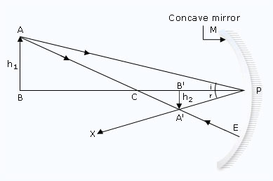
The magnification \(\mathrm{M}\) produced by a mirror is defined as the ratio of the height of the image to the height of the object:
\(\mathrm{M = \dfrac{h_i}{h_o} = -\dfrac{v}{u}}\)
- \(\mathrm{h_i}\) = height of image
- \(\mathrm{h_o}\) = height of object
- The negative sign shows that a real image is inverted, while a virtual image is upright.
Example :
An object is placed \(20 \, \mathrm{cm}\) in front of a concave mirror of focal length \(10 \, \mathrm{cm}\). Find the position and nature of the image.
▶️ Answer/Explanation
Step 1: Use the mirror formula: \(\mathrm{\dfrac{1}{f} = \dfrac{1}{v} + \dfrac{1}{u}}\)
\(\mathrm{\dfrac{1}{-10} = \dfrac{1}{v} + \dfrac{1}{-20}}\)
\(\mathrm{-\dfrac{1}{10} = \dfrac{1}{v} – \dfrac{1}{20}}\)
\(\mathrm{\dfrac{1}{v} = -\dfrac{1}{10} + \dfrac{1}{20} = -\dfrac{1}{20}}\)
\(\mathrm{v = -20 \, cm}\)
Step 2: The image is formed \(20 \, \mathrm{cm}\) in front of the mirror.
Step 3: Since \(v\) is negative, the image is real, inverted, and same size.
Ray Diagrams for Mirrors
Ray diagrams are graphical tools used to determine the location, type, size, and orientation of images formed by mirrors. They provide a visual method to understand image formation without solving equations.
Key Principles:
- Light travels in straight lines, and rays obey the laws of reflection.
- The intersection of reflected rays (or their extensions) determines the position of the image.
- The number and placement of rays chosen must be sufficient to determine the size and orientation of the image accurately.
Construction Rules for Ray Diagrams:
Plane Mirror:
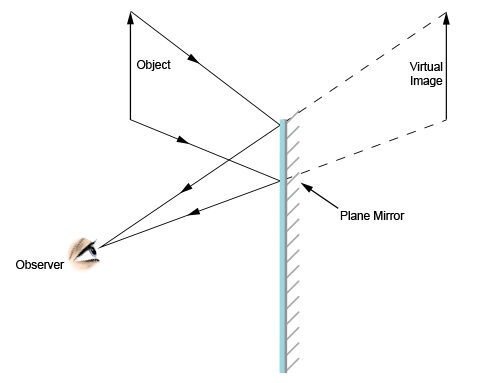
- Draw at least two rays from the top of the object.
- One ray perpendicular to the mirror reflects back on itself.
- Another ray at an angle reflects according to the law of reflection.
- Extend reflected rays behind the mirror to locate the virtual image.
Concave Mirror:
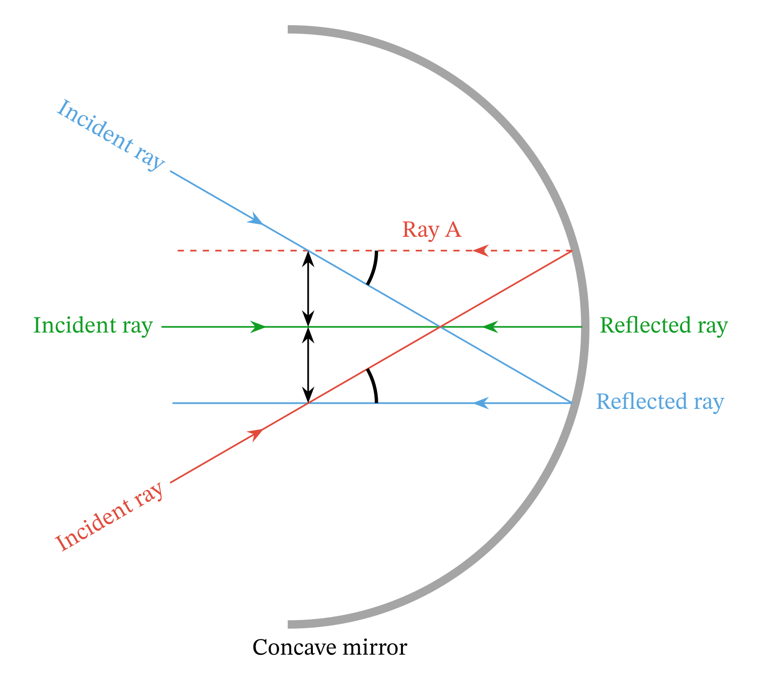
- Draw at least two rays from the top of the object:
- Ray parallel to the principal axis → passes through the focus after reflection.
- Ray through the focus → reflects parallel to the principal axis.
- Ray towards the center of curvature → reflects back along the same path.
- The intersection of reflected rays gives the image location.
Convex Mirror:

- Draw at least two rays from the top of the object:
- Ray parallel to the principal axis → reflects as if coming from the focus behind the mirror.
- Ray aimed at the focus behind the mirror → reflects parallel to the principal axis.
- The extensions of reflected rays behind the mirror intersect to form the virtual image.
Summary:
- Ray diagrams visually show image location, type (real/virtual), size, and orientation (upright/inverted).
- They are consistent with the mirror formula (\(\mathrm{\dfrac{1}{f} = \dfrac{1}{v} + \dfrac{1}{u}}\)) and magnification formula (\(\mathrm{M = -v/u}\)).
- Useful for quickly analyzing optical systems like mirrors in telescopes, periscopes, and everyday mirrors.
Example:
Construct a ray diagram for an object placed between the focus and pole of a concave mirror. Determine the image type, orientation, and relative size.
▶️ Answer/Explanation
Step 1: Draw the principal axis, pole, and focus of the concave mirror.
Step 2: Draw a ray from the top of the object parallel to the principal axis; it reflects through the focus.
Step 3: Draw a ray from the top through the focus; it reflects parallel to the principal axis.
Step 4: The intersection of the reflected rays (extended if necessary) gives the virtual, upright, and magnified image behind the mirror.