AP Physics 2- 11.4 Electric Power - Exam Style questions - FRQs- New Syllabus
Electric Power AP Physics 2 FRQ
Unit 11: Electric Circuits
Weightage : 15–18%
Question
Most-appropriate topic codes (AP Physics 2):
• Topic \( 11.5 \) — Compound Direct Current (DC) Circuits (Part \( \mathrm{(b)} \))
• Topic \( 11.6 \) — Kirchhoff’s Loop Rule (Part \( \mathrm{(b)} \))
• Skill \( 3.B \) — Apply an appropriate law, definition, theoretical relationship, or model to make a claim (Part \( \mathrm{(b)} \))
• Skill \( 3.C \) — Justify or support a claim using evidence from experimental data, physical representations, or physical principles or laws (Part \( \mathrm{(b)} \))
▶️ Answer/Explanation
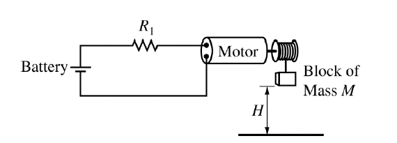
(a)
The block is lifted at constant speed, so the motor’s mechanical work goes into increasing the block’s gravitational potential energy.
The work done on the block is
\( W = MgH \)
Mechanical power is work done per unit time, so
\( P = \dfrac{W}{\Delta t} \)
Therefore,
\( \boxed{P = \dfrac{MgH}{\Delta t}} \)
Since \( M \) and \( H \) are fixed, decreasing \( \Delta t \) means the motor must deliver a larger power.
(b)
\( \boxed{\text{In parallel with } R_1} \)
To decrease \( \Delta t \), the motor must lift the same block through the same height in less time. From part \( \mathrm{(a)} \), that means the required mechanical power must increase:
\( P = \dfrac{MgH}{\Delta t} \)
The problem states that the mechanical power of the motor increases when the potential difference across the motor increases. Therefore, to reduce \( \Delta t \), we must increase the voltage across the motor.
The motor and \( R_1 \) are originally in series, so the battery voltage is shared between them. If a resistor \( R_2 \) is added in parallel with \( R_1 \), the equivalent resistance of that branch becomes smaller than \( R_1 \) alone:
\( R_{\text{eq}} = \dfrac{R_1 R_2}{R_1 + R_2} \)
so \( R_{\text{eq}} < R_1 \).
This reduces the resistance of the non-motor part of the series circuit, which increases the total current. Because the motor is still in series with the rest of the circuit, the current through the motor also increases. Since the motor has constant resistance, its voltage drop is
\( \Delta V_{\text{motor}} = I R_{\text{motor}} \)
so a larger current means a larger potential difference across the motor.
A larger voltage across the motor means a larger mechanical power output, so the motor lifts the block faster. Therefore, the time interval \( \Delta t \) decreases.
The other options do not help in the same way: putting \( R_2 \) in series would increase total resistance and reduce current, while putting it in parallel with the motor would not be the correct way to increase the motor’s power in this setup.