
AP Physics 2- 11.7 Kirchhoff’s Junction Rule- Exam Style questions - FRQs- New Syllabus
Kirchhoff’s Junction Rule AP Physics 2 FRQ
Unit 11: Electric Circuits
Weightage : 15–18%
Question
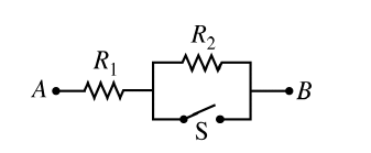
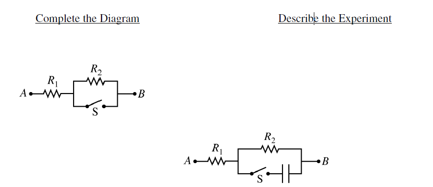
Most-appropriate topic codes (AP Physics 2):
• Topic \(11.5\) — Compound Direct Current \( \mathrm{(DC)} \) Circuits (Part \( \mathrm{(a)} \), Part \( \mathrm{(b)} \), Part \( \mathrm{(c)} \))
• Topic \(11.6\) — Kirchhoff’s Loop Rule (Part \( \mathrm{(a)} \), Part \( \mathrm{(b)(ii)} \), Part \( \mathrm{(b)(iii)} \))
• Topic \(11.7\) — Kirchhoff’s Junction Rule (Part \( \mathrm{(b)(i)} \), Part \( \mathrm{(b)(ii)} \))
▶️ Answer/Explanation
(a)
The ammeter and battery should be connected in series with the resistor combination between points \(A\) and \(B\). This allows the current through the entire circuit to be measured.
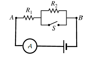
First, close the switch \(S\). When the switch is closed, it provides a conducting path in parallel with \(R_2\). Since the switch has negligible resistance, it shorts out \(R_2\), so almost no current flows through \(R_2\). The circuit resistance is then just \(R_1\).
Measure the current \(I_1\) with the switch closed. Using the \(9\,\text{V}\) battery, calculate
\(R_1=\dfrac{V}{I_1}\)
where \(V=9\,\text{V}\).
Next, open the switch \(S\). When the switch is open, current must pass through both \(R_1\) and \(R_2\), so the total resistance is \(R_1+R_2\).
Measure the current \(I_2\) with the switch open. Then
\(R_1+R_2=\dfrac{V}{I_2}\)
Therefore,
\(R_2=\dfrac{V}{I_2}-R_1\)
So the measurements needed are the current with the switch closed and the current with the switch open.
\(\boxed{R_1=\dfrac{9\,\text{V}}{I_1}}\), and \(\boxed{R_2=\dfrac{9\,\text{V}}{I_2}-R_1}\)
(b)(i)
Immediately after the switch is closed, the capacitor is initially uncharged, so it acts like a wire for the first instant. This means the switch-capacitor branch has current through it.
At that instant, the switch-capacitor branch effectively shorts out \(R_2\), so the current through \(R_2\) is \(0\).
Therefore, immediately after the switch is closed, the current through resistor \(1\) is \(0.9\,\text{A}\), the current through the switch is \(0.9\,\text{A}\), and the current through resistor \(2\) is \(0\,\text{A}\).
A long time after the switch is closed, the capacitor is fully charged and behaves like an open circuit. Therefore, no current flows through the capacitor branch or the switch.
At long time, current flows through \(R_1\) and \(R_2\) in series. Thus, the current through resistor \(1\) is \(0.3\,\text{A}\), the current through resistor \(2\) is \(0.3\,\text{A}\), and the current through the switch is \(0\,\text{A}\).
\(\boxed{\text{Immediately: } I_{R_1}=0.9\,\text{A},\ I_{R_2}=0,\ I_S=0.9\,\text{A}}\)
\(\boxed{\text{Long time: } I_{R_1}=0.3\,\text{A},\ I_{R_2}=0.3\,\text{A},\ I_S=0}\)
(b)(ii)
Immediately after the switch is closed, the capacitor branch acts like a wire and shorts out \(R_2\). Therefore, only \(R_1\) limits the current.
\(V=I_{\text{initial}}R_1\)
Substitute \(V=9\,\text{V}\) and \(I_{\text{initial}}=0.9\,\text{A}\):
\(9\,\text{V}=\left(0.9\,\text{A}\right)R_1\)
\(R_1=\dfrac{9\,\text{V}}{0.9\,\text{A}}\)
\(\boxed{R_1=10\,\Omega}\)
A long time after the switch is closed, the capacitor branch acts like an open circuit. Current then flows through \(R_1\) and \(R_2\) in series.
\(V=I_{\text{long}}\left(R_1+R_2\right)\)
Substitute \(V=9\,\text{V}\), \(I_{\text{long}}=0.3\,\text{A}\), and \(R_1=10\,\Omega\):
\(9\,\text{V}=\left(0.3\,\text{A}\right)\left(10\,\Omega+R_2\right)\)
Divide both sides by \(0.3\,\text{A}\):
\(30\,\Omega=10\,\Omega+R_2\)
\(\boxed{R_2=20\,\Omega}\)
(b)(iii)
A long time after the switch is closed, the capacitor branch has no current, but the capacitor is connected across the same two points as \(R_2\). Therefore, the potential difference across the capacitor equals the potential difference across \(R_2\).
The long-time current is \(0.3\,\text{A}\), and \(R_2=20\,\Omega\), so
\(V_C=V_{R_2}=I_{\text{long}}R_2\)
\(V_C=\left(0.3\,\text{A}\right)\left(20\,\Omega\right)\)
\(\boxed{V_C=6\,\text{V}}\)
This can also be found from the battery voltage minus the potential difference across \(R_1\):
\(V_C=9\,\text{V}-\left(0.3\,\text{A}\right)\left(10\,\Omega\right)=6\,\text{V}\)
(c)
The third group’s calculated value of \(R_1\) would be greater than the second group’s value.
The second group uses an ideal power supply, so the full \(9\,\text{V}\) is available across the external circuit. Immediately after the switch is closed, the current is \(0.9\,\text{A}\), giving \(R_1=10\,\Omega\).
The third group uses a battery that is not ideal. A real battery has internal resistance. Some of the battery’s emf is lost as a potential difference across the internal resistance inside the battery. Therefore, the terminal potential difference across the external circuit is less than \(9\,\text{V}\) when current flows.
Because the actual external potential difference is smaller, the measured current through the circuit is smaller than it would be for an ideal \(9\,\text{V}\) battery.
If the students still use \(R_1=\dfrac{9\,\text{V}}{I}\), but the current \(I\) is smaller because of the internal resistance, then the calculated resistance will be too large.
In effect, the students calculate the resistance of \(R_1\) plus the battery’s internal resistance, not just \(R_1\).
\(\boxed{\text{The third group calculates a value greater than }10\,\Omega\text{ because the internal resistance reduces the current.}}\)