AP Physics 2- 11.3 Resistance, Resistivity, and Ohm’s Law- FRQs- New Syllabus
Resistance, Resistivity, and Ohm’s Law AP Physics 2 FRQ
Unit 11: Electric Circuits
Weightage : 15–18%
Question
A. Describe a procedure for collecting data that would allow the student to determine the expected time constant \( \tau \). In your description, include the measurements to be made. Include any steps necessary to reduce experimental uncertainty.
| Table \( 1 \) | |
|---|---|
| \( |\Delta V| \) \( (\mathrm{V}) \) | \( q \) \( (\times 10^{-10}\ \mathrm{C}) \) |
| \( 3.0 \) | \( 2.4 \) |
| \( 5.0 \) | \( 4.2 \) |
| \( 7.2 \) | \( 5.6 \) |
| \( 8.0 \) | \( 6.6 \) |
| \( 10.0 \) | \( 8.0 \) |
• Clearly label the axes, including units as appropriate.
• Plot the points you recorded in Table \( 2 \).

Most-appropriate topic codes (AP Physics 2):
• Topic \( 11.3 \) — Resistance, Resistivity, and Ohm’s Law (Part \( \mathrm{A} \), Part \( \mathrm{B} \))
• Topic \( 11.8 \) — Resistor-Capacitor \( (\mathrm{RC}) \) Circuits (Part \( \mathrm{A} \), Part \( \mathrm{B} \))
▶️ Answer/Explanation
A.
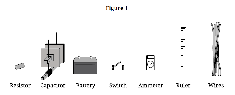
A valid procedure is to determine the resistance \( R \) of the resistor from the battery emf and the initial current, and to determine the capacitance \( C \) from the geometry of the air-filled parallel-plate capacitor.
First, measure the side length \( \ell \) of one square capacitor plate with the ruler. Then measure the plate separation \( d \) with the ruler. Since the plates are square, the plate area is \( A = \ell^2 \).
Next, connect the battery, resistor, ammeter, switch, and capacitor in series. Close the switch and record the initial current \( I_0 \) shown by the ammeter immediately after the circuit is completed.
Because the capacitor is initially uncharged, it behaves like a wire at that instant, so the initial current can be used to determine the resistor’s resistance. Then open the switch, fully discharge the capacitor, and repeat the current measurement several times. Average the values of \( I_0 \) to reduce random uncertainty.
Repeating the dimension measurements and averaging them also improves the estimate of \( \ell \) and \( d \).
B.
The expected time constant is
\( \tau = R_{\mathrm{eq}}C_{\mathrm{eq}} \)
Since there is only one resistor and one capacitor in series,
\( \tau = RC \)
Determine the resistance from the initial current:
\( R = \dfrac{\mathcal{E}}{I_0} \)
where \( \mathcal{E} \) is the known battery emf.
Determine the capacitance from the parallel-plate formula:
\( C = \kappa \epsilon_0 \dfrac{A}{d} \)
Since the dielectric constant of air is \( \kappa = 1 \),
\( C = \epsilon_0 \dfrac{\ell^2}{d} \)
Therefore,
\( \tau = \left(\dfrac{\mathcal{E}}{I_0}\right)\left(\epsilon_0 \dfrac{\ell^2}{d}\right) \)
\( \boxed{\tau = \dfrac{\epsilon_0 \mathcal{E}\,\ell^2}{I_0 d}} \)
So once \( \ell \), \( d \), and \( I_0 \) are measured, the student can calculate the expected time constant.
C(i)
One correct choice is:
Vertical axis: \( q \) \( (\times 10^{-10}\ \mathrm{C}) \)
Horizontal axis: \( |\Delta V| \) \( (\mathrm{V}) \)
because \( q = C|\Delta V| \), which is a linear relationship whose slope is \( C \).
C(ii)
A correct plotting table is:
| Table \( 2 \) | |
|---|---|
| \( |\Delta V| \) \( (\mathrm{V}) \) | \( q \) \( (\times 10^{-10}\ \mathrm{C}) \) |
| \( 3.0 \) | \( 2.4 \) |
| \( 5.0 \) | \( 4.2 \) |
| \( 7.2 \) | \( 5.6 \) |
| \( 8.0 \) | \( 6.6 \) |
| \( 10.0 \) | \( 8.0 \) |
A correct graph is shown below.
C(iii)
Draw a straight best-fit line through the plotted points, since the data are approximately linear.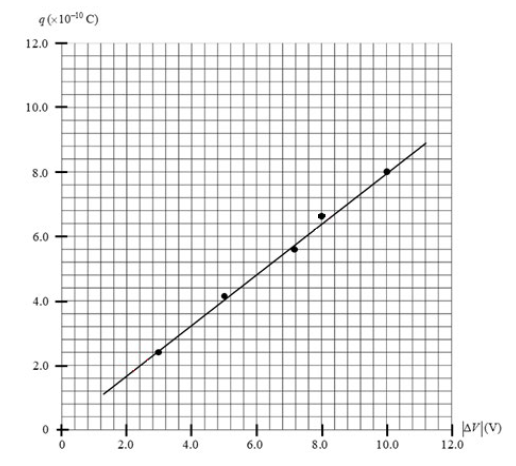
D.
Using \( q = C|\Delta V| \), the slope of a graph of \( q \) versus \( |\Delta V| \) is the capacitance \( C \).
Using two convenient points on the best-fit line, for example about \( (3.0,\ 2.4) \) and \( (10.0,\ 8.0) \) in the plotted units:
\( \text{slope} = \dfrac{\Delta q}{\Delta |\Delta V|} = \dfrac{(8.0-2.4)\times 10^{-10}\ \mathrm{C}}{10.0-3.0\ \mathrm{V}} \)
\( \text{slope} = \dfrac{5.6\times 10^{-10}}{7.0}\ \dfrac{\mathrm{C}}{\mathrm{V}} \approx 8.0\times 10^{-11}\ \mathrm{F} \)
Therefore,
\( \boxed{C \approx 8\times 10^{-11}\ \mathrm{F}} \)
This is reasonable because all the data points lie close to a single straight line, indicating an approximately constant capacitance.