AP Physics 2- 11.8 Resistor-Capacitor (RC) Circuits- FRQs- New Syllabus
Resistor-Capacitor (RC) Circuits AP Physics 2 FRQ
Unit 11: Electric Circuits
Weightage : 15–18%
Question
| Known Capacitance of Capacitors \( (\mu \mathrm{F}) \) | \( \Delta V_{\text{known}} \) \( (\mathrm{V}) \) | \( \Delta V_U \) \( (\mathrm{V}) \) | ||
|---|---|---|---|---|
| \( 200 \) | \( 0.91 \) | \( 3.53 \) | ||
| \( 300 \) | \( 0.65 \) | \( 3.74 \) | ||
| \( 400 \) | \( 0.51 \) | \( 3.95 \) | ||
| \( 500 \) | \( 0.42 \) | \( 4.06 \) | ||
| \( 600 \) | \( 0.36 \) | \( 4.17 \) |
(iii) Using your best-fit line, determine the capacitance of capacitor \( C_U \).
Most-appropriate topic codes (AP Physics 2):
• Topic \( 11.8 \) — Resistor-Capacitor \( (\mathrm{RC}) \) Circuits (Part \( \mathrm{(b)} \), Part \( \mathrm{(c)} \))
▶️ Answer/Explanation
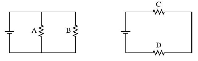
(a)
Ranking:
\[ 1\ \Delta V_A \qquad 1\ \Delta V_B \qquad 3\ \Delta V_C \qquad 2\ \Delta V_D \]
So,
\[ \Delta V_A = \Delta V_B > \Delta V_D > \Delta V_C \]
In the left circuit, resistors \( A \) and \( B \) are in parallel, so they each have the full battery potential difference across them. Therefore, \[ \Delta V_A = \Delta V_B \]
In the right circuit, resistors \( C \) and \( D \) are in series, so the battery voltage is shared. Since \[ R_D = 2R_C \] the larger resistor gets the larger potential difference, so \[ \Delta V_D > \Delta V_C \]
Also, any branch in the series circuit gets less than the full battery voltage, so both \( \Delta V_C \) and \( \Delta V_D \) are less than \( \Delta V_A \) and \( \Delta V_B \).
(b)(i)
Using \[ Q = C\Delta V \]
\[ Q = \left( 200\times 10^{-6}\ \mathrm{F} \right)\left( 0.91\ \mathrm{V} \right) \]
\[ Q = 1.82\times 10^{-4}\ \mathrm{C} \]
\[ \boxed{Q = 1.82\times 10^{-4}\ \mathrm{C}} \]
(b)(ii)
The data support a series connection because the two capacitor voltages add to approximately the battery voltage \( 4.5\ \mathrm{V} \) for every trial. For example,
\[ 0.91 + 3.53 = 4.44\ \mathrm{V} \]
\[ 0.65 + 3.74 = 4.39\ \mathrm{V} \]
\[ 0.51 + 3.95 = 4.46\ \mathrm{V} \]
This is what we expect for capacitors in series: the individual potential differences add to the battery potential difference.
(b)(iii)
If the capacitors were connected in parallel, both capacitors would always have the same potential difference. A voltmeter would only tell the common voltage, not the charge on the unknown capacitor. Since capacitance is found from \[ C = \frac{Q}{\Delta V} \] and \( Q \) would still be unknown, there would not be enough information to determine \( C_U \).
(c)(i)
A good linear graph is:
Vertical axis: \[ Q_{\text{known}} \] Horizontal axis: \[ \Delta V_U \]
because for series capacitors the charge magnitudes are equal, so \[ Q_{\text{known}} = Q_U = C_U \Delta V_U \] which is in the form \[ y = mx \] with slope \( = C_U \).
First calculate \[ Q_{\text{known}} = C_{\text{known}}\Delta V_{\text{known}} \] for each trial:
| \( C_{\text{known}} \) \( (\mu \mathrm{F}) \) | \( \Delta V_{\text{known}} \) \( (\mathrm{V}) \) | \( \Delta V_U \) \( (\mathrm{V}) \) | \( Q_{\text{known}} \) \( (\mu \mathrm{C}) \) | |
|---|---|---|---|---|
| \( 200 \) | \( 0.91 \) | \( 3.53 \) | \( 182 \) | |
| \( 300 \) | \( 0.65 \) | \( 3.74 \) | \( 195 \) | |
| \( 400 \) | \( 0.51 \) | \( 3.95 \) | \( 204 \) | |
| \( 500 \) | \( 0.42 \) | \( 4.06 \) | \( 210 \) | |
| \( 600 \) | \( 0.36 \) | \( 4.17 \) | \( 216 \) |
(c)(ii)
Plot \( Q_{\text{known}} \) versus \( \Delta V_U \). The points are approximately:
\[ \left( 3.53,\ 182 \right),\ \left( 3.74,\ 195 \right),\ \left( 3.95,\ 204 \right),\ \left( 4.06,\ 210 \right),\ \left( 4.17,\ 216 \right) \]
with \( \Delta V_U \) in volts and \( Q_{\text{known}} \) in microcoulombs.
A straight best-fit line should be drawn through these points.
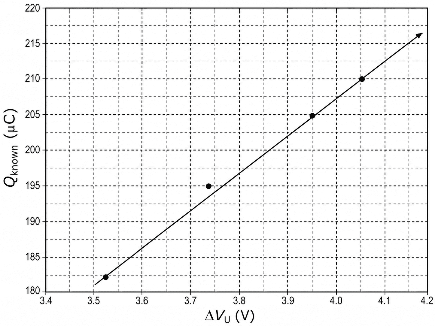
(c)(iii)
The capacitance \( C_U \) equals the slope of the graph:
\[ C_U = \frac{\Delta Q}{\Delta (\Delta V_U)} \]
Using two representative points on the best-fit line, for example \( (3.67,\ 190) \) and \( (4.10,\ 212) \),
\[ C_U = \frac{212\ \mu \mathrm{C} – 190\ \mu \mathrm{C}}{4.10\ \mathrm{V} – 3.67\ \mathrm{V}} \]
\[ C_U = \frac{22\ \mu \mathrm{C}}{0.43\ \mathrm{V}} \approx 51.2\ \mu \mathrm{F} \]
\[ \boxed{C_U \approx 51\ \mu \mathrm{F}} \]
That value makes sense because the unknown capacitor always has a much larger voltage than the known one, so its capacitance should be much smaller than the listed known capacitances.