Equivalent Resistance of Multiple Resistors
Equivalent resistance is the single resistance that can replace a combination of resistors in a circuit without changing the overall current-voltage relationship of the circuit.
Resistors in Series:

- In series, resistors are connected end-to-end so the same current flows through each.
- The total potential difference is the sum of voltage drops across each resistor.
\( \mathrm{R_{eq} = R_1 + R_2 + R_3 + \dots} \)
- Key Idea: Equivalent resistance is greater than any individual resistance.
Resistors in Parallel:

- In parallel, resistors are connected across the same two points, so the same potential difference is applied across each.
- The total current divides among the resistors, with each branch carrying part of the current.
\( \mathrm{\dfrac{1}{R_{eq}} = \dfrac{1}{R_1} + \dfrac{1}{R_2} + \dfrac{1}{R_3} + \dots} \)
- Key Idea: Equivalent resistance is always smaller than the smallest individual resistance.
Mixed Series–Parallel Combinations:
- For circuits with both series and parallel connections, reduce step by step:
- First simplify parallel groups, then add in series (or vice versa), until only one equivalent resistance remains.
Key Idea: Equivalent resistance simplifies circuit analysis by reducing complex resistor networks to a single value that governs the overall current for a given voltage source.
Example
Three resistors of \( 2.0 \, \Omega \), \( 4.0 \, \Omega \), and \( 6.0 \, \Omega \) are connected in series. Find the equivalent resistance.
▶️ Answer/Explanation
Step 1: Formula: \( \mathrm{R_{eq} = R_1 + R_2 + R_3} \).
Step 2: Substitute: \( \mathrm{R_{eq} = 2.0 + 4.0 + 6.0 = 12.0 \, \Omega} \).
Final Answer: The equivalent resistance is \( \mathrm{12.0 \, \Omega} \).
Example
Two resistors of \( 6.0 \, \Omega \) and \( 3.0 \, \Omega \) are connected in parallel. Find the equivalent resistance.
▶️ Answer/Explanation
Step 1: Formula: \( \mathrm{\dfrac{1}{R_{eq}} = \dfrac{1}{R_1} + \dfrac{1}{R_2}} \).
Step 2: Substitute: \( \mathrm{\dfrac{1}{R_{eq}} = \dfrac{1}{6} + \dfrac{1}{3} = \dfrac{1}{6} + \dfrac{2}{6} = \dfrac{3}{6}} \).
Step 3: \( \mathrm{R_{eq} = 2.0 \, \Omega} \).
Final Answer: The equivalent resistance is \( \mathrm{2.0 \, \Omega} \).
Example
A \( 6.0 \, \Omega \) resistor is connected in series with a parallel combination of \( 3.0 \, \Omega \) and \( 6.0 \, \Omega \). Find the total equivalent resistance.
▶️ Answer/Explanation
Step 1: Equivalent of parallel part: \( \mathrm{\dfrac{1}{R_p} = \dfrac{1}{3} + \dfrac{1}{6} = \dfrac{1}{2}} \quad \Rightarrow \quad R_p = 2.0 \, \Omega \).
Step 2: Total series resistance: \( \mathrm{R_{eq} = 6.0 + 2.0 = 8.0 \, \Omega} \).
Final Answer: The equivalent resistance of the circuit is \( \mathrm{8.0 \, \Omega} \).
Circuits with Resistive Wires and Batteries with Internal Resistance
Ideal vs. Non-Ideal Components:
- Ideal Battery: Supplies a constant potential difference equal to its emf (\(\mathcal{E}\)), with negligible internal resistance.
- Ideal Wires: Have negligible resistance, so they do not reduce current or potential difference in the circuit.
- Real Wires: Good conductors have very small but nonzero resistance. This resistance can usually be neglected if the circuit contains much larger resistive elements.
- Non-Ideal Battery: A real battery has internal resistance \( r \), which reduces the terminal potential difference when current flows.
Battery emf vs. Terminal Voltage: 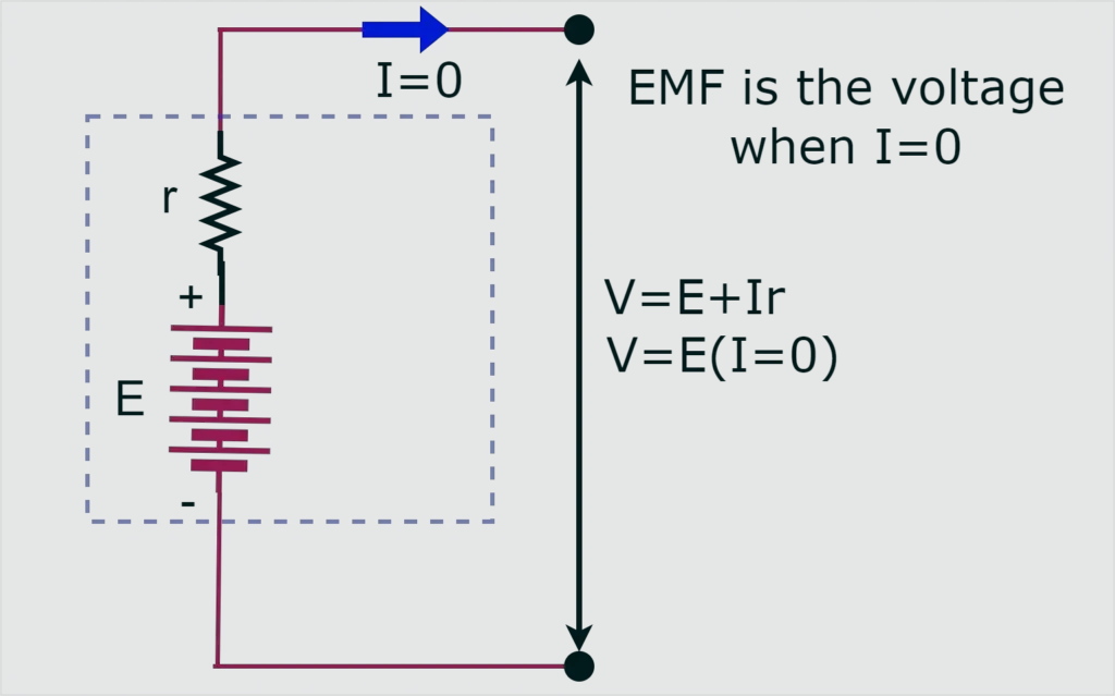
- The emf of a battery (\(\mathcal{E}\)) is the potential difference across its terminals when no current flows (open-circuit condition).
- The terminal voltage (\(V_{terminal}\)) is the actual potential difference across the battery when current \(I\) is flowing.
\( \mathrm{V_{terminal} = \mathcal{E} – I r} \)
- \(\mathrm{r}\) = internal resistance of the battery.
When current flows, part of the emf is “lost” as a potential drop inside the battery.
Key Concepts: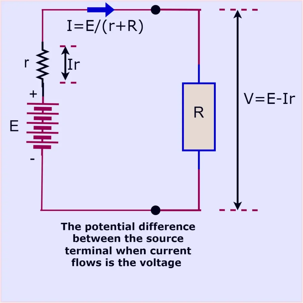
- Internal resistance can be modeled as a small resistor in series with an ideal emf source.
- The effect of internal resistance becomes significant when the current is large or when external resistance is small.
- The power dissipated inside the battery is:
\( \mathrm{P_{internal} = I^2 r} \)
- The useful power delivered to the external circuit is:
\( \mathrm{P_{external} = I V_{terminal} = I (\mathcal{E} – I r)} \)
Ideal models simplify circuits by neglecting wire and battery resistance. In reality, batteries have internal resistance that reduces the effective terminal voltage and limits the maximum current available.
Example
A battery with emf \( \mathcal{E} = 12 \, V \) and internal resistance \( r = 0.50 \, \Omega \) is connected to a \( 5.0 \, \Omega \) resistor. Find the terminal voltage of the battery.
▶️ Answer/Explanation
Step 1: Total resistance: \( \mathrm{R_{total} = R + r = 5.0 + 0.50 = 5.5 \, \Omega} \).
Step 2: Current: \( \mathrm{I = \dfrac{\mathcal{E}}{R_{total}} = \dfrac{12}{5.5} \approx 2.18 \, A} \).
Step 3: Terminal voltage: \( \mathrm{V_{terminal} = \mathcal{E} – I r = 12 – (2.18)(0.50)} \).
Step 4: \( \mathrm{V_{terminal} \approx 12 – 1.09 = 10.9 \, V} \).
Final Answer: The battery’s terminal voltage is approximately \( \mathrm{10.9 \, V} \).
Example
A 6.0 V battery with internal resistance \( 0.25 \, \Omega \) is short-circuited (connected directly across its terminals with negligible external resistance). Find the current through the circuit.
▶️ Answer/Explanation
Step 1: External resistance \( R = 0 \).
Step 2: Total resistance = \( r = 0.25 \, \Omega \).
Step 3: Current: \( \mathrm{I = \dfrac{\mathcal{E}}{r} = \dfrac{6.0}{0.25} = 24 \, A} \).
Final Answer: The short-circuit current is \( \mathrm{24 \, A} \). This very large current can quickly overheat the battery and wires.
Measurement of Current and Potential Difference
Ammeters:
An ammeter is used to measure the electric current at a specific point in a circuit.
- It must be connected in series with the circuit element whose current is being measured, so that the same current passes through both the element and the ammeter.
- Ideal Ammeter: Has zero resistance so it does not change the current in the circuit.
- Nonideal Ammeter: Has a small but finite resistance, which slightly reduces the current flowing through the circuit.
Voltmeters: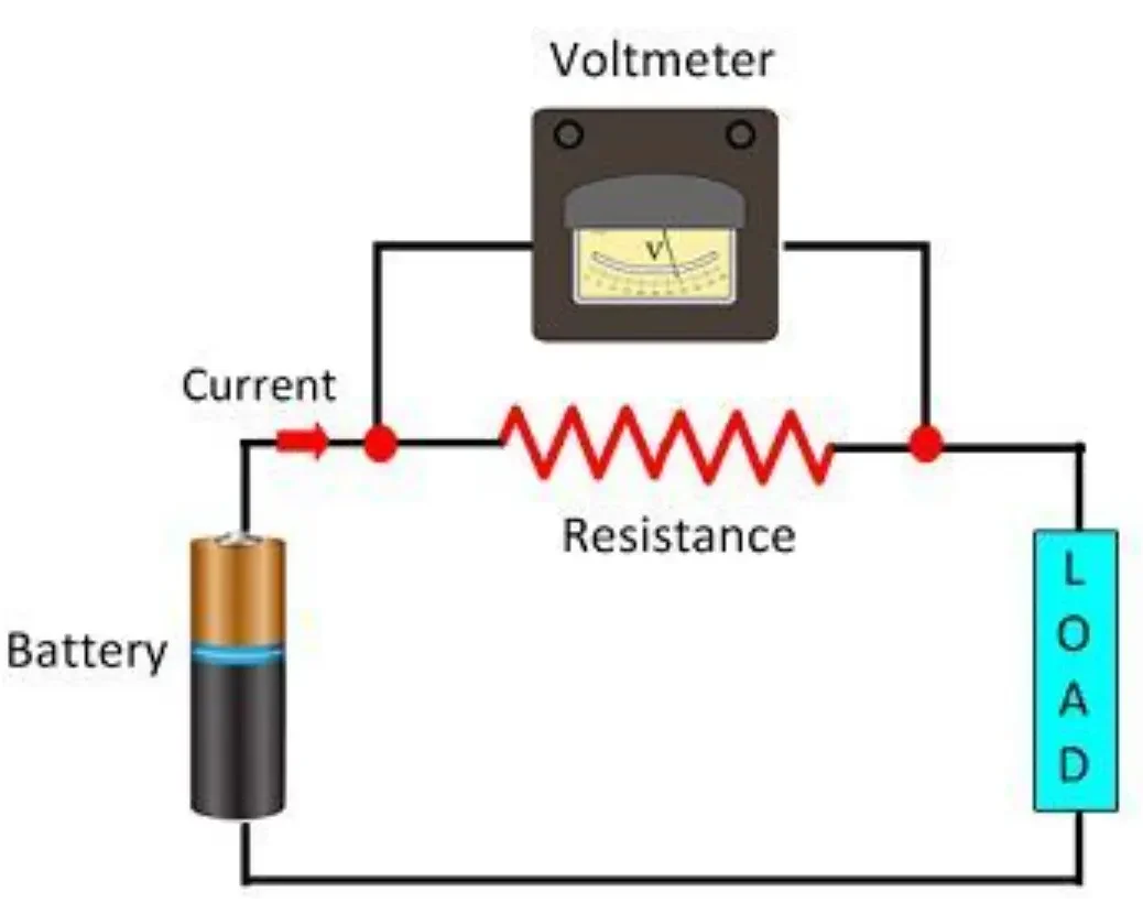
A voltmeter is used to measure the potential difference (voltage) between two points in a circuit.
- It must be connected in parallel with the element across which the potential difference is to be measured.
- Ideal Voltmeter: Has infinite resistance, so no current flows through the voltmeter, and the circuit remains undisturbed.
- Nonideal Voltmeter: Has very large but finite resistance, so a small current flows through it, slightly changing the circuit behavior.
Key Idea: Ideal meters do not disturb the circuit they measure. Real (nonideal) meters alter the circuit slightly because of their finite resistance.
Example
A current of \(2.0 \, A\) flows through a resistor in a series circuit. An ammeter with negligible resistance is placed in series with the resistor. What current will the ammeter read?
▶️ Answer/Explanation
Step 1: In series, the same current flows through all elements.
Step 2: Since the ammeter is ideal (zero resistance), it does not alter the current.
Final Answer: The ammeter will read \(2.0 \, A\).
Example
A \(12 \, V\) battery is connected across a \(6.0 \, \Omega\) resistor. A voltmeter is connected across the resistor. Assuming the voltmeter is ideal, what will it read?
▶️ Answer/Explanation
Step 1: The resistor is connected directly across the battery, so the potential difference across it equals the battery voltage.
Step 2: Since the voltmeter is ideal (infinite resistance), no current flows through it, so the circuit is not disturbed.
Final Answer: The voltmeter will read \(12 \, V\).