LR Circuits: Combination of a Resistor and an Inductor
An LR circuit contains a resistor and an inductor connected in series with a source of emf. The resistor dissipates electrical energy as heat, while the inductor resists changes in current by storing energy in its magnetic field.
Kirchhoff’s Loop Rule and Derived Equation: 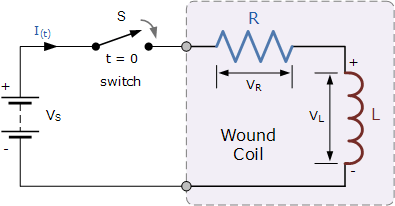
Applying Kirchhoff’s loop rule to a series LR circuit with a battery of emf \(\mathrm{\mathcal{E}}\):
\( \mathrm{\mathcal{E} – L \dfrac{dI}{dt} – IR = 0} \)
- This is a first-order differential equation describing the current \(I(t)\) in the circuit.
Time Constant of an LR Circuit:
The time constant is defined as:
\( \mathrm{\tau = \dfrac{L}{R}} \)
- \(\mathrm{\tau}\) represents the time scale over which current approaches its steady-state value.
Current Behavior in an LR Circuit:
Charging (with zero initial current):
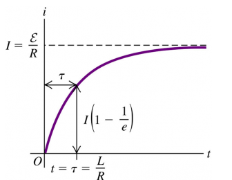
\( \mathrm{I(t) = I_{max}\big(1 – e^{-t/\tau}\big)} \), where \( \mathrm{I_{max} = \dfrac{\mathcal{E}}{R}} \).
- After a time \(t = \tau\), current reaches about 63% of its final value.
Discharging (with initial current \(I_0\)):
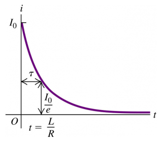
\( \mathrm{I(t) = I_0 e^{-t/\tau}} \).
- After a time \(t = \tau\), current decreases to about 37% of its initial value.
Energy Consideration:
The energy initially stored in the inductor’s magnetic field is:
\( \mathrm{U = \dfrac{1}{2} L I^2} \)
- This energy is dissipated as thermal energy in the resistor as the current decays.
Example:
An LR circuit has a \(12 \, V\) battery, a resistor of \(6.0 \, \Omega\), and an inductor of \(0.30 \, H\). Find
(a) the time constant, and
(b) the current after \(0.20 \, s\) if the switch is closed at \(t=0\).
▶️ Answer/Explanation
Part (a): Time constant
\( \mathrm{\tau = \dfrac{L}{R} = \dfrac{0.30}{6.0} = 0.050 \, s} \).
Part (b): Current at \(t=0.20\,s\)
Final current: \( \mathrm{I_{max} = \dfrac{\mathcal{E}}{R} = \dfrac{12}{6.0} = 2.0 \, A} \).
Current growth: \( \mathrm{I(t) = I_{max}(1 – e^{-t/\tau})} \).
Substitute: \( \mathrm{I(0.20) = 2.0 \left(1 – e^{-0.20/0.050}\right)} \).
\( \mathrm{I(0.20) = 2.0 (1 – e^{-4}) \approx 2.0 (1 – 0.0183) = 1.96 \, A} \).
Time-Dependent Electric Properties of Inductors
An inductor resists changes in current due to the emf induced by its own changing magnetic flux. While the current in an inductor is changing, its electrical properties (voltage, current, energy) vary exponentially with time. After a long time compared to the circuit’s time constant, the inductor reaches steady state and behaves like a simple conducting wire with negligible resistance.
Inductor Behavior at Switching:
- At the instant a switch is closed: The inductor initially opposes the sudden change in current. The induced emf is equal in magnitude and opposite in direction to the applied potential difference.
- At the instant a switch is opened: The inductor again resists the change in current, maintaining current flow briefly by inducing a large emf.
Exponential Behavior of Inductors in Circuits:
Potential difference across the inductor: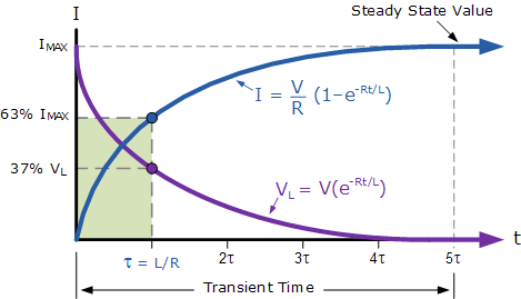
\( \mathrm{V_L(t) = \mathcal{E} e^{-t/\tau}} \) (during current growth in LR circuit)
Current through the inductor:
\( \mathrm{I(t) = I_{max}(1 – e^{-t/\tau})} \) (growth) \( \mathrm{I(t) = I_0 e^{-t/\tau}} \) (decay)
Energy stored in the inductor:
\( \mathrm{U(t) = \tfrac{1}{2} L I(t)^2} \)
- All of these quantities approach asymptotic steady-state values as \( t \gg \tau \).
Steady-State Behavior:
After a time much greater than the time constant (\( \tau = L/R \)), the current reaches its final steady-state value
\( \mathrm{I_{max} = \dfrac{\mathcal{E}}{R}} \).
- At this point, the inductor no longer resists current changes and acts like a simple wire of zero resistance.
Key Idea: Inductors affect circuits only during transient conditions (when current is changing). In steady state, they have no potential difference across them and behave as ideal conductors.
Example:
A \(12 \, V\) battery, a \(6.0 \, \Omega\) resistor, and a \(0.30 \, H\) inductor are connected in series. Find the potential difference across the inductor at
(a) \(t = 0\) and
(b) \(t \gg \tau\).
▶️ Answer/Explanation
Step 1: Time constant
\( \mathrm{\tau = \dfrac{L}{R} = \dfrac{0.30}{6.0} = 0.050 \, s} \).
Step 2: At \(t = 0\):
Current is initially zero, so the inductor opposes the full applied emf: \( \mathrm{V_L(0) = \mathcal{E} = 12 \, V} \).
Step 3: At \(t \gg \tau\):
Inductor behaves like a wire; current reaches \(I_{max} = \dfrac{\mathcal{E}}{R} = 2.0 \, A\).
At steady state, \( \mathrm{V_L = 0 \, V} \).