Question
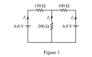
The circuit shown above is constructed with two 6.0 V batteries and three resistors with the values shown. The currents I1 , I2 , and I3 in each branch of the circuit are indicated.
(a)
i. Using Kirchhoff’s rules, write, but DO NOT SOLVE, equations that can be used to solve for the current in each resistor.
ii. Calculate the current in the 200 Ω resistor.
iii. Calculate the power dissipated by the 200 Ω resistor.
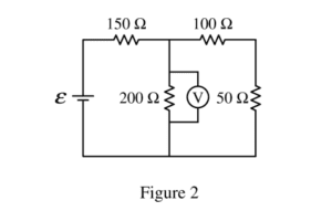
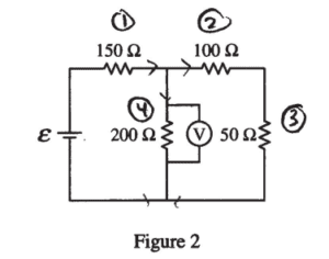
The two 6.0 V batteries are replaced with a battery with voltage ε and a resistor of resistance 50 Ω, as shown above. The voltmeter V shows that the voltage across the 200 Ω resistor is 4.4 V.
(b) Calculate the current through the 50 Ω resistor.
(c) Calculate the voltage e of the battery.
(d)
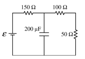
i. The 200 Ω resistor in the circuit in Figure 2 is replaced with a 200 Fμ capacitor, as shown on the right, and the circuit is allowed to reach steady state. Calculate the current through the 50 Ω resistor.
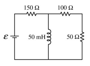
ii. The 200 W resistor in the circuit in Figure 2 is replaced with an ideal 50 mH inductor, as shown on the right, and the circuit is allowed to reach steady state. Is the current in the 50 W resistor greater than, less than, or equal to the current calculated in part (b) ?
____ Greater than ____ Less than ____ Equal to
Justify your answer.
Answer/Explanation
Ans:
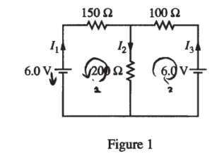
(a) i.
Loop 1: 6 – 150 I1 – 200 I2 = 0
Loop 2: 6 – 100 I3 – 200 I2 = 0
I1 + I3 = I2
ii.
I1 = I2 – I3
– 6 – 150 I2 + 150 I3 – 200 I2 = 0
6 – 150 I3 – 200 I2 = 0
——————————————
-150I2 + 250 I3 = 0
I3 = 0.6 I2
6 – 100 (0.6I2 ) – 200 I2 = 0
I2 = 0.023 (A)
iii.
P = I2R = (0.023)2 (200) = 0.107 (w)
(b)
R25 = 100 + 50 = 150 Ω
V23 = V4 = 4.4 (V)
\(I_{2}=I_{3}=\frac{V_{23}}{R_{23}}=\frac{4.4}{150}=0.029 (A)\)
(c)
\(I_{1}=I_{2}+I_{4}=I_{2}+\frac{V_{4}}{R_{4}}=0.029+\frac{4.4}{200}\)
= 0.051 (A)
\(I_{1}=I_{1}R_{1}=0.051(150)=7.7(V)\rightarrow \varepsilon =V_{1}+V_{4}=7.7 + 4.4 = 12.1 (V)\)
(d)
i. E = 12.1 (V) Capacitor is a broken circuit 7)
∑R = 150 + 100 + 50 = 300 (Ω)
\(I_{1}=I_{2}=I_{3}=\frac{12.1}{300}= 0.04 (A)\)
ii. __√__ Greater than
Because the inductor is a short circuit at steady state, the loop is series – parallel, thus, the total resistance decreases, current increases
Question

In the circuit shown above, the switch S is initially in the open position shown, and the capacitor is uncharged. A voltmeter (not shown) is used to measure the correct potential difference across
resistor R1.
a. On the circuit diagram above, draw the voltmeter with the proper connections for correctly measuring
the potential difference across resistor R1.
b. At time t = 0, the switch is moved to position A. Determine the voltmeter reading for the time
immediately after t = 0.
c. After a long time, a measurement of potential difference across R1 is again taken. Determine for this
later time each of the following.
i. The voltmeter reading
ii. The charge on the capacitor
d. At a still later time t = T, the switch S is moved to position B. Determine the voltmeter reading for the
time immediately after t = T.
e. A long time after t = T, the current in R1 reaches a constant final value If
i. Determine If.
ii. Determine the final energy stored in the inductor.
f. Write, but do not solve, a differential equation for the current in resistor R1 as a function of time t after
the switch is moved to position B.
Answer/Explanation
Ans.
a.

b. The capacitor is ignored: I = ε/(R1 + R2) = 20 V/30 Ω = 0.67 A
V = IR = 6.67 V
c. i. V = 0 (the capacitor is charged, current is zero.
ii. Q = CV = (15 μF)(20 V) = 300 μC
d. V = 0
e. i. The inductor is ignored: I = ε/(R1 + R2) = 20 V/30 Ω = 0.67 A
ii. UL = ½ LI2 = 0.444 J
f. ε – I(R1 + R2) – L(dI/dt) = 0