Question
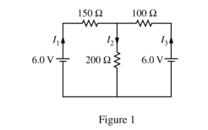
The circuit shown above is constructed with two 6.0 V batteries and three resistors with the values shown. The currents I1 , I2 , and I3 in each branch of the circuit are indicated.
(a)
i. Using Kirchhoff’s rules, write, but DO NOT SOLVE, equations that can be used to solve for the current in each resistor.
ii. Calculate the current in the 200 Ω resistor.
iii. Calculate the power dissipated by the 200 Ω resistor.
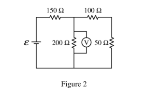
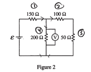
The two 6.0 V batteries are replaced with a battery with voltage ε and a resistor of resistance 50 Ω, as shown above. The voltmeter V shows that the voltage across the 200 Ω resistor is 4.4 V.
(b) Calculate the current through the 50 Ω resistor.
(c) Calculate the voltage e of the battery.
(d)
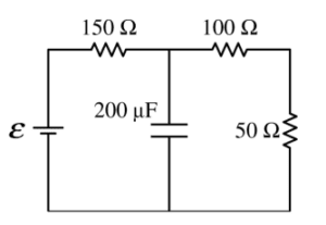
i. The 200 Ω resistor in the circuit in Figure 2 is replaced with a 200 Fμ capacitor, as shown on the right, and the circuit is allowed to reach steady state. Calculate the current through the 50 Ω resistor.
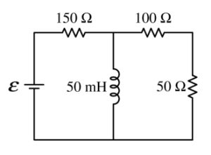
ii. The 200 W resistor in the circuit in Figure 2 is replaced with an ideal 50 mH inductor, as shown on the right, and the circuit is allowed to reach steady state. Is the current in the 50 W resistor greater than, less than, or equal to the current calculated in part (b) ?
____ Greater than ____ Less than ____ Equal to
Justify your answer.
Answer/Explanation
Ans:
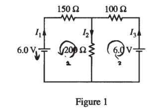
(a) i.
Loop 1: 6 – 150 I1 – 200 I2 = 0
Loop 2: 6 – 100 I3 – 200 I2 = 0
I1 + I3 = I2
ii.
I1 = I2 – I3
– 6 – 150 I2 + 150 I3 – 200 I2 = 0
6 – 150 I3 – 200 I2 = 0
——————————————
-150I2 + 250 I3 = 0
I3 = 0.6 I2
6 – 100 (0.6I2 ) – 200 I2 = 0
I2 = 0.023 (A)
iii.
P = I2R = (0.023)2 (200) = 0.107 (w)
(b)
R25 = 100 + 50 = 150 Ω
V23 = V4 = 4.4 (V)
\(I_{2}=I_{3}=\frac{V_{23}}{R_{23}}=\frac{4.4}{150}=0.029 (A)\)
(c)
\(I_{1}=I_{2}+I_{4}=I_{2}+\frac{V_{4}}{R_{4}}=0.029+\frac{4.4}{200}\)
= 0.051 (A)
\(I_{1}=I_{1}R_{1}=0.051(150)=7.7(V)\rightarrow \varepsilon =V_{1}+V_{4}=7.7 + 4.4 = 12.1 (V)\)
(d)
i. E = 12.1 (V) Capacitor is a broken circuit 7)
∑R = 150 + 100 + 50 = 300 (Ω)
\(I_{1}=I_{2}=I_{3}=\frac{12.1}{300}= 0.04 (A)\)
ii. __√__ Greater than
Because the inductor is a short circuit at steady state, the loop is series – parallel, thus, the total resistance decreases, current increases
Question

A technician uses the circuit shown above to test prototypes of a new battery design. The switch
is closed, and the technician records the current for a period of time. The curve that best fits the results
is shown in the graph below.
The equation for this curve is I = Ioe–kt where t is the time elapsed from the instant the switch is closed
and Io and k are constants.

a. i. Using the information in the graph, determine the potential difference Vo across the resistor
immediately after the switch is closed.
ii. Would the open circuit voltage of the fresh battery have been less than, greater than, or equal to the
value in part i? Justify your answer.
b. Determine the value of k from this best-fit curve. Show your work and be sure to include units in your
answer.
c. Determine the following in terms of R, Io, k, and t.
i. The power delivered to the resistor at time t = 0
ii. The power delivered to the resistor as a function of time t
iii. The total energy delivered to the resistor from t = 0 until the current is reduced to zero
Answer/Explanation
Ans.
a. i. V = IR, from the graph I0 ≈ 9.3 A so V = (9.3 A)(3.3 Ω) ≈ 31 V
ii. The battery’s open circuit voltage would be greater as a real battery has internal resistance so when it is
connected in a circuit only part of the open circuit voltage appears across the external components
b. Taking the natural log of the expression for current gives ln(I) = ln(I0) – kt ln(e), or ln(I/I0) = –kt
k = ln(I/I0)/t and take a reading from the graph (for example 7.5 A at 0.5 h) gives k = 0.4 hr–1
c. i. P = I2R at t =0 gives P = I02R
ii. substituting the expression for current gives P = I02Re-2kt
iii.
