Question

3. A wire is connected to a resistor of resistance R to form a rigid square loop of side length D. An external force is exerted on the loop so that the loop always moves with constant speed v in the +x direction, as shown in Figure 1. The loop then enters Region 1 of external uniform magnetic field of magnitude B that is directed in the +z-direction. Region 1 has boundaries x = D and x = 2D. The loop later enters Region 2 of external uniform magnetic field of magnitude 2B that is directed in the +z-direction. Region 2 has boundaries x = 2D and x = 3.5D. Point S is the midpoint of the leading edge of the loop.
(a) On the following axes, sketch a graph of the magnetic flux Φ through the square loop as a function of the position x of Point S from x = 0 to x = 4.5D. The +z-direction indicated in Figure 1 corresponds to +Φ.

(b)Consider the instant when Point S reaches x = 1.5D.
i. Indicate whether the current IS that is induced in the square loop when Point S reaches x = 1.5D is clockwise, counterclockwise, or zero.
_____ Clockwise _____ Counterclockwise _____ Zero
Briefly justify your answer.
ii. Derive an expression for \(I_{S}\) when Point S reaches x = 1.5L. If \(I_{S}\) = 0, indicate how the derived expression shows that \(I_{S}\) = 0. Express your answer in terms of R, L, v, B, and physical constants, as appropriate.
iii. Derive an expression for the power P dissipated by the resistor when Point S reaches x = 1.5D. Express your answer in terms of R, D, v, B, and physical constants, as appropriate.
The total energy dissipated by the resistor in the square loop as Point S moves from x = 0 to x = 4.5D is \(E_{original}\).
The vertical boundary between regions 1 and 2 is now shifted to x = 2.5D. After the boundary is shifted, the square loop again moves with speed v in the +x-direction, as shown in Figure 2. The total energy dissipated by the resistor as Point S moves from x = 0 to x = 4.5D is is \(E_{new}\).

(c) Indicate whether \(E_{new}\).is greater than, less than, or equal to \(E_{original}\).
_____ \(E_{new}\). > \(E_{original}\)._____ \(E_{new}\). < \(E_{original}\). _____ \(E_{new}\). = \(E_{original}\).
Briefly justify your answer.
The original magnetic fields are modified so that the region D < < x 3.5D contains an external uniform magnetic field of magnitude B that is directed in the +z-direction.
A new wire is connected to a resistor of resistance R to form a rigid triangular loop with base length D and height D. An external force is exerted on the loop so that the loop always moves with speed v in the +x-direction, as shown in Figure 3. Point S represents the upper-leading corner of the loop.

(d) On the following axes, sketch a graph of the induced current \(I_{T}\) in the loop as Point S moves from x = D to x = 3D.

▶️Answer/Explanation
3(a) Example Response

Scoring Note: A response that is reflected across the horizontal axis can earn the four points.
Scoring Note: The absolute values of the slopes in the entire regions D x < < 3D and 3.5D x < < 4.5D are not considered for earning these points.
3(b)(i) Example Response
Clockwise. The magnetic flux through the loop is increasing in the +z -direction. Therefore, a magnetic field is induced by the current in the loop to oppose the increasing magnetic flux. To establish this field, the current must be clockwise.
3(b)(ii) Example Solution

(b)(iii) Example Solution
\(p = I^{2}R\)
\( p = \left ( -\frac{BDv}{R} \right )^{2}\)
\(p =\frac{2B^{2}L^{2}v^{2}}{R}\)
(c) Example Response
The change in magnetic flux is greater in the original scenario, which produces an emf and current for a longer time. Therefore, \(E_{new}\) < \(E_{original}\)
(d) Example Response 
Scoring Note: A response that is reflected across the horizontal axis earns both points.
Scoring Note: Any portion of the graph before x D = and after x = 3D will not be scored.
Question
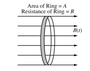
A thin, conducting ring of area A and resistance R is aligned in a uniform magnetic field directed to the right and perpendicular to the plane of the ring, as shown. At time t = 0, the magnitude of the magnetic field is B0. At t = 1 s, the magnitude of the magnetic field begins to decrease according to the equation \(B(t)=\frac{\beta }{t}\) , where β has units of T · s.
(a) Derive an equation for the magnitude of the induced current I in the ring as a function of t for t > 1 s.
Express your answer in terms of β, A, R, t, and physical constants, as appropriate.
Assume A = 0.50 m2, R = 2.0 Ω, and β = 0.50 T · s.
(b) Calculate the electrical energy dissipated in the ring from t = 1 s to t = 2 s.
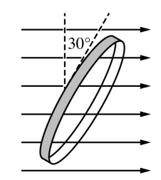
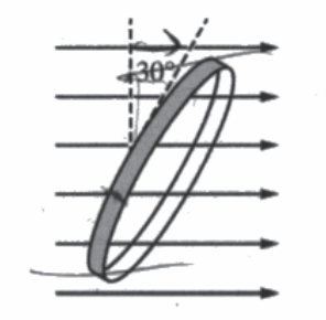
The ring is then rotated so that the plane of the ring is aligned at a 30° angle to the magnetic field, as shown. The magnitude of the magnetic field is reset to a magnitude of B0 at a new time t = 0 and again begins to decrease at t = 1 s according to the equation \(B(t)=\frac{\beta }{t}\) , where β has units of T · s.
(c) Will the amount of energy dissipated in the ring from t = 1 s to t = 2 s be greater than, less than, or equal to the energy dissipated in part (b) ?
_____ Greater than _____ Less than _____ Equal to
Justify your answer.
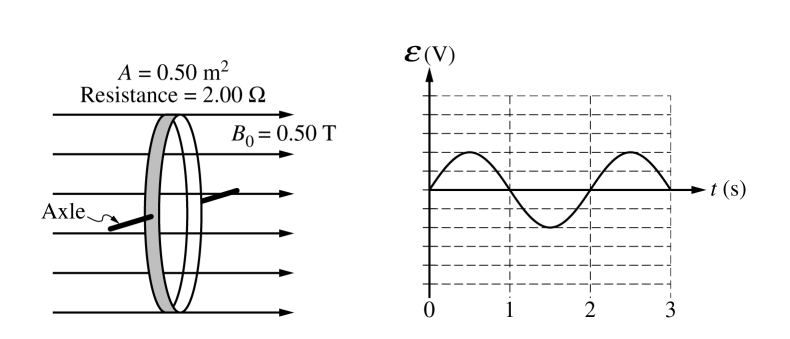
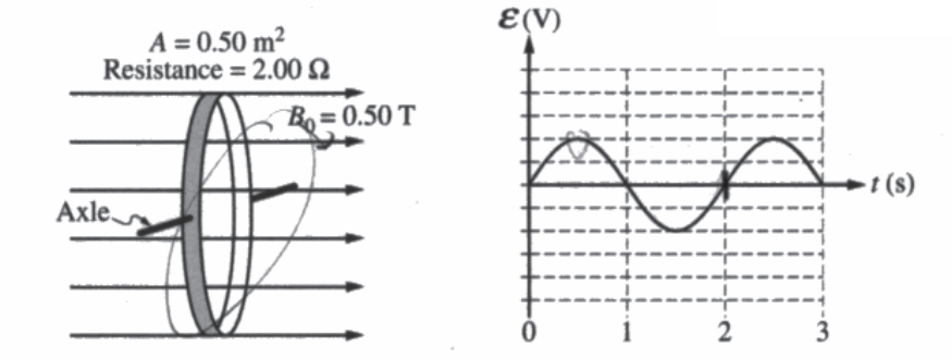
The ring is now mounted on an axle that is perpendicular to the magnetic field. The magnitude of the magnetic field is now held at a constant B0 = 0.50 T, as shown. The ring rotates about the axle, and the emf ε induced in the ring as a function of time t is shown on the graph.
(d) Calculate the angular speed ω of the rotating ring in rad/s.
(e) Calculate the magnitude of the maximum emf εMAX induced in the ring.
The ring now begins to rotate at an angular speed 2ω.
(f) On the graph below, draw a curve to indicate the new induced emf ε in the ring. The dashed curve shows the emf induced under the original conditions.
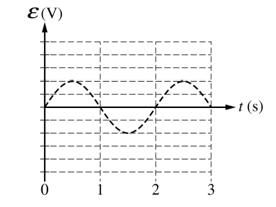
Justify your sketch, specifically identifying and addressing any similarities or differences between the sketch and the original graph.
Answer/Explanation
Ans:
(a)
\(\left | \varepsilon \right |=\left | \frac{dI_{B}}{dt} \right |= \left | \frac{d}{dt} (SB\cdot dA)\right |=\left | \frac{d}{dt} BA\right |=\left | A\frac{dB}{dt} \right |=\left | -A\frac{B}{t^{2}} \right |=\left | A\frac{\beta }{t^{2}} \right |\)
\(\varepsilon /R = i \Rightarrow \frac{A\beta }{Rt^{2}}\)
(b) P = I2R = electrical energy dissipated \(\int P dt = \int I^{2}R dt\)
\(=\int \frac{A^{2}\beta ^{2}}{Rt^{4}}dt\)
0.121 J \(\Leftarrow \frac{(0.5)^{2}(0.5)^{2}}{2}\left ( \frac{4}{1}-\frac{4}{32} \right )\) \(\frac{A^{2}B^{2}}{R}\int_{t=1}^{t=2}\frac{1}{t^{4}}dt\)
\(P = \left ( \frac{AB}{Rt^{2}} \right )R=\frac{A^{2}B^{2}}{Rt^{4}}\) \(\frac{A^{2}B^{2}}{R}\left ( \frac{-4}{t^{5}} \right )_{1}^{2}\)
(c)
√ Less than
Now only a portion of the saw magnetic field (Bit) sin(30), to be exact) does through the loop. This decreases the EMF, the current, and thus the power dissipate.
(d)
Period T = 2s as per 2nd graph \(w = \frac{2\pi radius}{2s}=\pi \frac{rod}{sec}\)
(e)
\(\varepsilon = \frac{dI_{b}}{dt}\cdot B\frac{dA}{dt}\) A = A cos (wt)
\(\frac{dA}{dt}=-Asin(wt) (w)\)
ε = BA w sin (wt) wt = π/2
0.185 v = (0.5) (0.5)(π)(1) = π/4 t = 1/2
w = π
(f)
ε = BA ws, hurt
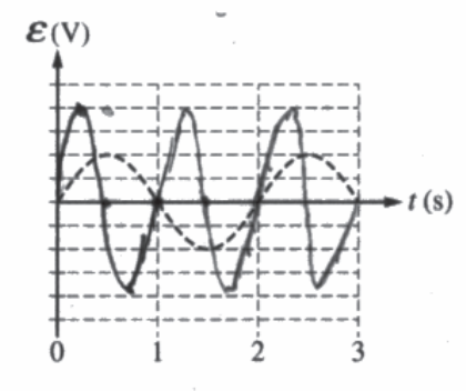
The period will now be solved
The amplitude will double because ε ∝ w. This makes serve because the area will be changing more rapidly, so a greater Emf will be induced.
Question
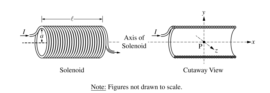
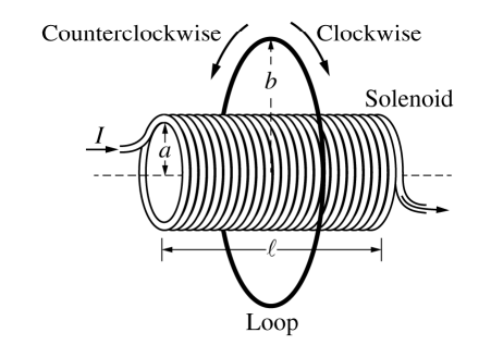
A solenoid is used to generate a magnetic field. The solenoid has an inner radius a, length l , and N total turns of wire. A power supply, not shown, is connected to the solenoid and generates current I, as shown in the figure on the left above. The x-axis runs along the axis of the solenoid. Point P is in the middle of the solenoid at the origin of the xyz-coordinate system, as shown in the cutaway view on the right above. Assume l >> a .
(a) Select the correct direction of the magnetic field at point P.
____ +x-direction ____ +y-direction ____ +z-direction
____ –x-direction ____ –y-direction ____ –z-direction
Justify your selection.
(b)
i. On the cutaway view below, clearly draw an Amperian loop that can be used to determine the magnetic field at point P at the center of the solenoid.

ii. Use Ampere’s law to derive an expression for the magnetic field strength at point P. Express your answer in terms of I, l, N, a, and physical constants, as appropriate.
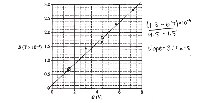
Some physics students conduct an experiment to determine the resistance RS of a solenoid with radius a = 0.015 m, total turns N = 100, and total length l = 0.40 m. The students connect the solenoid to a variable power supply. A magnetic field sensor is used to measure the magnetic field strength along the central axis at the center of the solenoid. The plot of the magnetic field strength B as a function of the emf ε of the power supply is shown below.
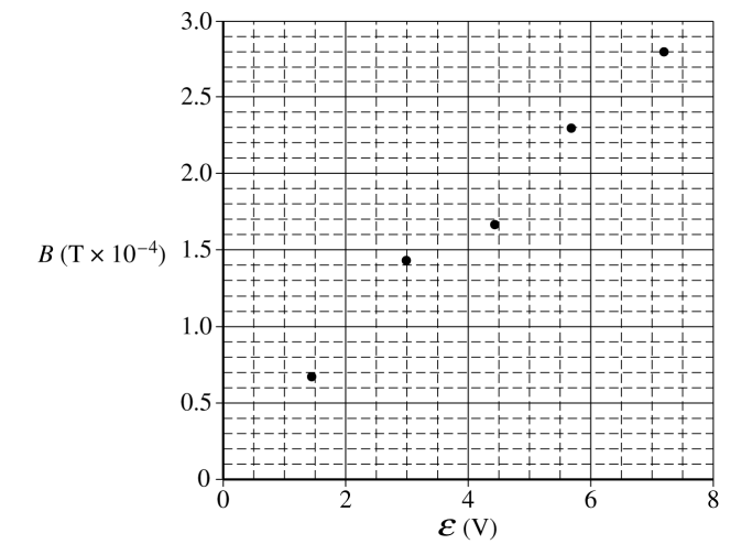
(c)
i. On the graph above, draw a best-fit line for the data.
ii. Use the straight line to determine the resistance RS of the solenoid used in the experiment.
(d) One of the students notes that the horizontal component of the magnetic field of Earth is 2.5 × 10⁻⁵ T .
i. Is there evidence from the graph that the horizontal orientation of the solenoid affects the measured values for B ?
____ Yes ____ No
Justify your answer.
ii. Would the horizontal orientation of the solenoid affect the calculated value for RS ?
____ Yes ____ No
Justify your answer
A thin conducting loop of radius b and resistance RL is placed concentric with the solenoid, as shown above. The current in the solenoid is decreased from I to zero over time Δt.
(e)
i. Is the direction of the induced current in the loop clockwise or counterclockwise during the time period that the current in the solenoid is decreasing?
____ Clockwise ____ Counterclockwise
Justify your answer.
ii. Derive an equation for the average induced current iIND in the loop during the time period that the current in the solenoid is decreasing. Express your answer in terms of I, l, N, a, b, RL , RS , Δt, and physical constants, as appropriate.
Answer/Explanation
Ans:
(a) Using the right hand rule, curl your fingers in the direction of the current, thumb points in the direction of \(\overrightarrow{B}\) field
(b) i. 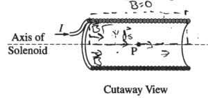
ii.
\(\int \overrightarrow{B}\cdot d\overrightarrow{s}=M_{0}I\) N = number of turns
\(\int \overrightarrow{B}\cdot d\overrightarrow{s}=M_{0}NI\) only place θ = 0 is
along axis of solnoid
\(\int B cos\theta ds = M_{0}NI\)
\(\int B ds = M_{0}NI\)
Bl = M0NI
\(B_{s} = \frac{M_{0}NI}{l}\)
(c) i.
ii.
\(B_{s} = \frac{M_{0}NI}{l}=\frac{M_{0}NV}{lR}\) Bvs.V \(slope=\frac{M_{0}N}{lR}\)
\(R=\frac{M_{0}N}{l(slope)}\)
\(R=\frac{\left ( 4\pi \times 10^{-7}(100) \right )}{(.40)(3.7-5)}=8.5 \mu \)
(d)
i. __X___ Yes
The best fit line will not have a y-intercept of zero. The y-intercept will be 2.5 × 10⁻⁵ T
ii. __X___ No
The y-intercept of the graph has no effect on the slope
(e)
i. __X___ Clockwise
According to Lenz’s Law. a decreasing field to the right will induce a field in the same direction in order to maintain \(\frac{d\Phi }{d_{4}}net = 0\)
ii.
\(\sum = \frac{\Delta \Phi }{\Delta t} = \frac{\Delta (BA) }{\Delta t}=A\frac{\Delta \left ( M_{0} \frac{N}{l}I\right ) }{\Delta t}=\frac{AM_{0}N}{l} \frac{\Delta I}{\Delta l}\)
\(I=\frac{\varepsilon }{R}=\frac{AM_{0}N}{R_{L}l} \frac{\Delta I}{\Delta l}=\frac{(\pi a^{2})M_{0}N}{R_{L}l}\left ( \frac{\Delta I}{\Delta t} \right )\)