Question
(12 points-suggested time 25 minutes)
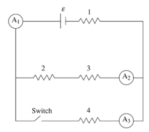
The figure shows a circuit with a battery of emf ε and negligible internal resistance, and four identical resistors of resistance R numbered 1, 2, 3, and 4. There are three ammeters (A1, A2, and A3) that measure the currents I1, I2, and I3, respectively. The circuit also has a switch that begins in the closed position.
(A) A student makes this claim: “The current I3 is twice as large as I2.” Do you agree or disagree with the student’s statement? Support your answer by applying Kirchhoff s loop rule and writing one or more algebraic expressions to support your argument.
(B) Rank the power dissipated into heat by the resistors from highest to lowest, being sure to indicate any that are the same. Justify your ranking.
The switch is opened. A student makes this statement: “The power dissipation of resistors 2 and 3 remains the same because they are in parallel with the switch. The power dissipation of resistor 1 decreases because opening the switch cuts off some of the current going through resistor 1.”
(C) i. Which parts of the student’s statement do you agree? Justify your answer with appropriate physics principles.
ii. Which parts of the student’s statement do you disagree with? Justify your answer utilizing an algebraic argument.
The switch remains open. Resistor 4 is replaced with an uncharged capacitor of capacitance C. The switch is now closed.
(D) i. Determine the current in resistor 1 and the potential difference across the capacitor immediately after the switch is closed.
ii. Determine the current in resistor 1 and the potential difference across the capacitor a long time after the switch is closed.
iii. Calculate the energy CU) stored on the capacitor a long time after the switch is closed.
Answer/Explanation
Ans:
Part (A)
Agree.
1 point-For correctly applying Kirchhoffs loop rule for the upper loop:
ε – I2R – I2R – I1R = 0
ε = 2I2R – I1R
1 point-For correctly applying Kirchhoff’s loop rule to the outer loop:
ε – I3R – I1R = 0
ε = I3R – I1R
1 point-For correctly using the two equations to show that I3 is twice as large as I2:
2I2R – I1R = I3R – I1R
2I2R = I3R
2I2 = I3
Part (B)
No points are awarded for the correct ranking of: P1 > P4 > P2 = P3.
1 point-For indicating that Power= I2R and that all the resistors are the same. Therefore, the ranking is based on the current passing through the resistors.
1 point-For indicating that resistor 1 receives the most current as all the current must pass through it AND that resistor 4 receives more current than resistors 2 and 3 AND that resistors 2 and 3 receive the same current because they are in the same conductive pathway.
Part (C)
(i.) Agree that the power will go down for resistor 1.
1 point-For indicating that when the switch is opened, there is only one path left for the current to pass through. This means the total resistance of the circuit increases. The potential difference across resistor 1 will decrease, which will bring its power dissipation down as well.
(ii.) Disagree that resistors 2 and 3 are unaffected.
1 point-For deriving a correct expression for the original current passing through resistors 2 and 3:
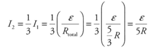
1 point-For deriving a correct expression for the new current passing through resistors 2 and 3:
\(I_{2}=I_{1}=\frac{\varepsilon }{R_{total}}=\frac{\varepsilon }{3R}\)
The new current is larger than the old; therefore, the power dissipation goes up. (Note that this argument can be also be made using potential difference and would also receive credit.)
Part (D)
(i.) Immediately after the switch is closed, the capacitor acts like a short-circuit wire that allows the current to bypass resistors 2 and 3.
1 point-For indicating that the current through resistor 1 will be \(I_{1}=\frac{\varepsilon }{R},\) and that the potential difference across the capacitor is zero (ΔVC =0).
(ii.) After a long period of time, the capacitor becomes fully charged and acts like an open switch in the circuit.
1 point-For indicating the current through resistor 1 will be: \(I_{1}=\frac{\varepsilon }{3R}.\)
1 point-For indicating that the potential difference across the capacitor will be equal to that of resistors 2 and 3 combined, because the capacitor is in parallel with them: \(\Delta V_{C}=\frac{2}{3}\varepsilon .\) Note this can be stated in words or symbolically to receive credit.
(iii.)
1 point-For calculating the potential energy stored by the capacitor: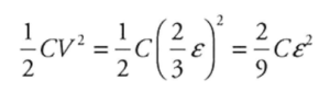
Question
Consider the following circuit:

(a) Determine the current that passes through \(R_{3}\) and \(R_{1}\).
(b) At what rate does \(R_{4}\) resistor dissipate energy?
(c) What is the voltage read by the voltmeter in the circuit?
(d) In order to minimize the impact of the voltmeter on the circuit, should the voltmeter have a very high or very low internal resistance?
Answer/Explanation
Ans:
(a) First, label some points in the circuit.

There are three branches each with their own current, \(fabc(I_{1})\), \(cdef(I_{2})\), \(cf(I_{3})\). By the Junction Rule: \(I_{3}=I_{1}-I_{2}\).
By the Loop Rule, the total change around any closed loop must be zero. You can then write equations for the following loops:
\(abcfa\): \(-I_{1}R_{3}-I_{1}R_{4}-(I_{1}-I_{2})R_{2}-(I_{1}-I_{2})R_{1}+V_{1}=0\)
\(cdefc\): \(V_{2}+(I_{1}-I_{2})R_{2}+(I_{1}-I_{2})R_{1}=0\)
Adding the two equations, you get
\(-I_{1}(35\Omega )+25V=0\)
\(25V=I_{1}(35\Omega )\)
\(I_{1}=\frac{5}{7}A\)
Plugging this into the cdefc equation, you get
\(15V+(I_{1})(15\Omega )-(I_{2})(15\Omega )=0\)
\(15V+\frac{5}{7}A(15\Omega )-(I_{2})(15)=0\)
\(1V+\frac{5}{7}V-(I_{2})(1\Omega )=0\)
\((I_{2})(1\Omega )=\frac{12}{7}V\)
\(I_{2}=\frac{12}{7}A\)
So the current through \(R_{3}\) is \(\frac{5}{7}\)A and \(R_{3}\) is \(\frac{12}{7}\)A.
(b) The rate at which \(R_{4}\) dissipates energy is given by \(P=IR^{2}=\frac{5}{7}A(20\Omega )^{2}=285.7W\)
(c) The voltmeter will read the sum of the voltage drops across \(R_{3}\) and \(R_{4}\)
\(V_{3+4}=V_{3}+V_{4}=I^{3}R^{3}+I^{4}R^{4}=(\frac{5}{7}A)(15\Omega )+(\frac{5}{7}A)(20\Omega )=25v\)
(d) The voltmeter is connected in parallel with the circuit. To minimize the impact of the voltmeter on the circuit, the voltmeter should have a very high resistance. Consider the following calculation of the total resistance upon addition of the voltmeter:
\(\frac{1}{R_{eff}}=\frac{1}{R_{+4}}+\frac{1}{R_{volmeter}}\)
If \(R_{volmeter}\) was very high, the \(R_{eff}\) would be very close in value to \(R_{3+4}\):
\(V_{R3}+V_{R4}=I_{1}R_{3}+I_{1}R_{4}=\frac{5}{7}A(15\Omega )+\frac{5}{7}A(20\Omega )=25V\)