
AP Physics C- E&M- 12.1 Magnetic Fields - Exam Style questions - FRQs- New Syllabus
Question
_____ $-x$-direction _____ $-y$-direction _____ $-z$-direction
ii. Use the straight line to determine the resistance $R_S$ of the solenoid used in the experiment.
Most-appropriate topic codes (AP Physics C: Electricity and Magnetism):
• Topic 12.3 — Magnetic Fields of Current-Carrying Wires and the Biot–Savart Law (Part b)
• Topic 12.4 — Ampère’s Law (Part b)
• Topic 11.3 — Resistance, Resistivity, and Ohm’s Law (Part c)
• Topic 13.1 — Magnetic Flux (Part e)
• Topic 13.2 — Electromagnetic Induction (Part e)
▶️ Answer/Explanation
Here is a comprehensive breakdown of the solutions. We analyze how the field builds inside the solenoid, how to interpret experimental data, and how changing magnetic fields induce emf in surrounding loops.
(a)
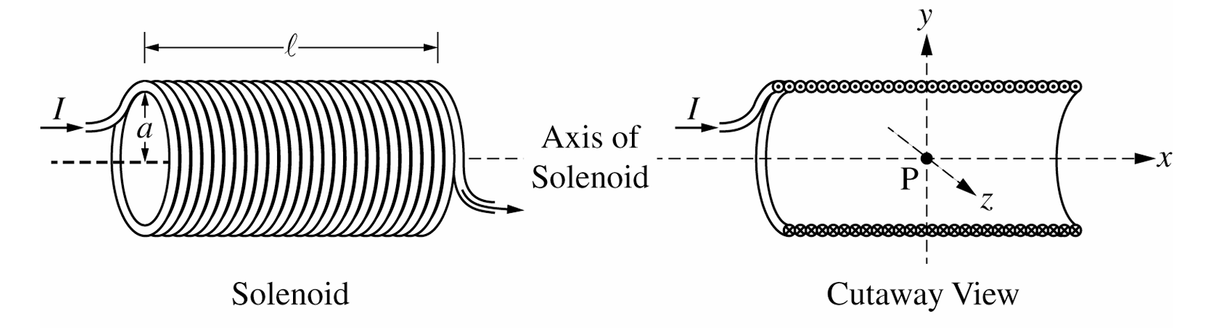
Correct choice: $\underline{\checkmark}$ $+x$-direction
Using the right-hand rule for solenoids, curl the fingers of your right hand in the direction of the current running through the individual loops of wire. Your thumb will then point straight along the central axis of the solenoid. In the provided diagram, this corresponds directly to the positive $+x$-direction.
(b)i.
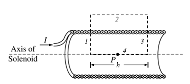
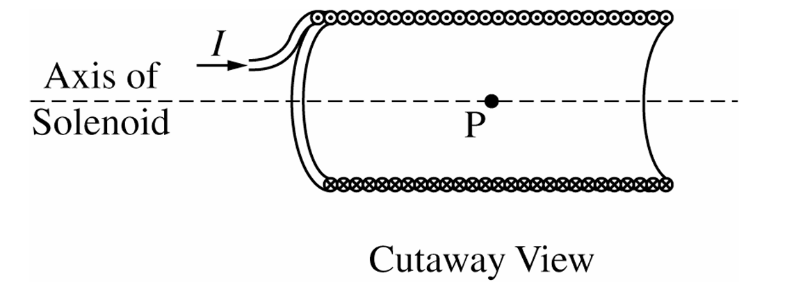
To capture the field correctly using Ampere’s law, draw a rectangular Amperian loop. One long side of length $L_A$ must pass straight through the interior of the solenoid parallel to the axis (containing point P), while the opposite parallel side lies completely outside the solenoid where the magnetic field is negligible. The two short sides cross the solenoid walls perpendicularly.
(b)ii.
Apply Ampere’s Law:
$\oint \vec{B} \cdot d\vec{l} = \mu_0 I_{enc}$
Only the interior segment parallel to the axis contributes significantly to the line integral:
$B L_A = \mu_0 \left( \frac{N}{l} L_A \right) I$
Cancel the length of the Amperian loop $L_A$ from both sides to find the final field formula:
$\boxed{B = \frac{\mu_0 N I}{l}}$
(c)i.
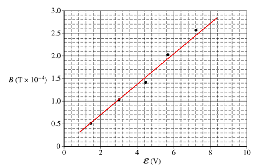
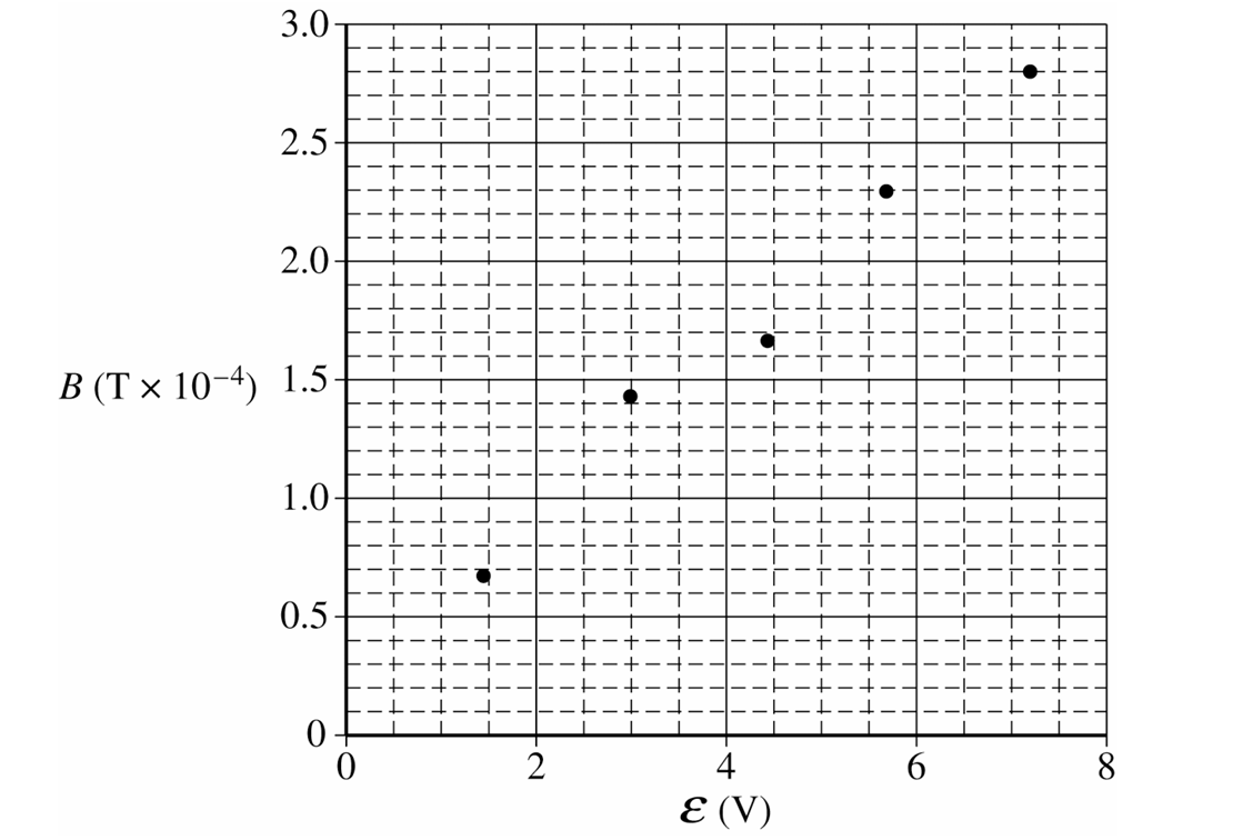
Draw a straight best-fit line passing smoothly through the given data points. The line should intercept very close to the origin $(0,0)$.
(c)ii.
First, find the numerical slope using the best-fit line, not the data points unless they fall on the best-fit line:
\(\text{slope}=\frac{\Delta B}{\Delta \mathcal{E}}\)
\(\text{slope}\approx \frac{(2.5-0.9)\times 10^{-4}\text{ T}}{(6.4-2.0)\text{ V}}\)
\(\text{slope}\approx \frac{1.6\times 10^{-4}\text{ T}}{4.4\text{ V}}\)
\(\text{slope}\approx 0.36\times 10^{-4}\text{ T/V}\)
\(\text{slope}\approx 3.6\times 10^{-5}\text{ T/V}\)
Now relate the slope to the resistance of the solenoid.
For a solenoid,
\(B=\frac{\mu_0NI}{l}\)
Using Ohm’s law,
\(I=\frac{\mathcal{E}}{R_S}\)
Substitute into the solenoid field equation:
\(B=\frac{\mu_0N\mathcal{E}}{lR_S}\)
Therefore,
\(\text{slope}=\frac{B}{\mathcal{E}}=\frac{\mu_0N}{lR_S}\)
Rearrange to solve for \(R_S\):
\(R_S=\frac{\mu_0N}{l\cdot \text{slope}}\)
\(R_S=\frac{(4\pi\times 10^{-7})(100)}{(0.40)(3.6\times 10^{-5})}\)
\(R_S\approx 8.7\ \Omega\)
\(\boxed{R_S\approx 8.7\ \Omega}\)
(d)i.
Correct choice: $\underline{\checkmark}$ No
If Earth’s background magnetic field was significantly biasing our sensor, the line would not pass through the origin when the power supply is completely turned off ($\mathcal{E} = 0$). Because the data points clearly trend down to $B = 0$ at zero voltage, any external magnetic field component along the axis is negligible within experimental error limits.
(d)ii.
Correct choice: $\underline{\checkmark}$ No
Earth’s magnetic field is a constant background value. Since the resistance $R_S$ depends mathematically on the change in field divided by the change in voltage ($\Delta B / \Delta \mathcal{E}$), adding a constant vertical offset to the graph leaves the overall slope perfectly unchanged.
(e)i.
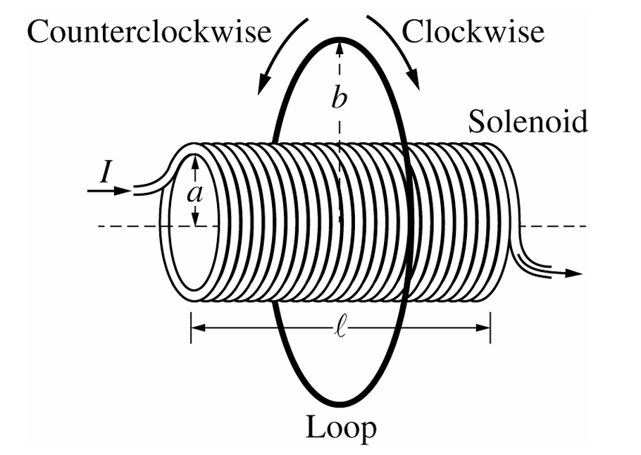
Correct choice: $\underline{\checkmark}$ Counterclockwise
As the primary current decreases, the magnetic flux pointing towards the $+x$-direction inside the loop starts dropping. According to Lenz’s law, the induced current opposes this loss by generating its own field in the $+x$-direction. Applying the right-hand rule shows that a counterclockwise current view from the left generates this supportive field.
(e)ii.
Start with Faraday’s Law to relate the induced electromotive force to the changing magnetic flux:
$\mathcal{E}_{ind} = \left| \frac{\Delta \Phi_B}{\Delta t} \right|$
The magnetic field is bounded within the solenoid’s cross-sectional area, $A = \pi a^2$:
$\Delta \Phi_B = \Delta B \cdot (\pi a^2) = \left( \frac{\mu_0 N I}{l} – 0 \right) \pi a^2 = \frac{\mu_0 N I \pi a^2}{l}$
Substitute the flux change into Faraday’s law to determine the magnitude of the induced voltage:
$\mathcal{E}_{ind} = \frac{\mu_0 N I \pi a^2}{l \Delta t}$
Finally, use Ohm’s law with the loop’s own electrical resistance $R_L$ to find the average current:
$\boxed{i_{ind} = \frac{\mu_0 N I \pi a^2}{l R_L \Delta t}}$