Nature of Forces and Interactions
A force is a vector quantity that represents an interaction between two objects or systems. It has both magnitude and direction and can change an object’s motion or shape. Forces are the fundamental way in which objects influence one another in physics.
- Forces describe interactions such as gravitational, normal, tension, frictional, or electromagnetic effects.
- Each force acts along a line and can be represented by a vector arrow indicating direction and magnitude.
- The net force on an object determines its acceleration: \( \mathrm{\vec{F}_{net} = m\vec{a}} \).
Forces Arise from Interactions Between Objects
A force acting on an object or system is always caused by an interaction with another object or system. No object can experience a force in isolation — every force has both a source and a receiver.
- Each force involves two participants (the object exerting the force and the object experiencing it).

- Contact forces (e.g., tension, normal, friction) arise through physical contact.
- Field forces (e.g., gravity, electric, magnetic) act through a field without direct contact.
An Object Cannot Exert a Net Force on Itself
A system or object cannot exert a net force on itself. While internal forces may exist between parts of a system, they always occur in equal and opposite pairs, cancelling each other according to Newton’s Third Law. Only external forces can change the motion of a system’s center of mass.
- Internal forces affect only relative motion within the system, not its overall acceleration.
- The motion of the system as a whole is determined solely by external forces.
\( \mathrm{\sum \vec{F}_{net} = \sum \vec{F}_{ext}} \)
Example
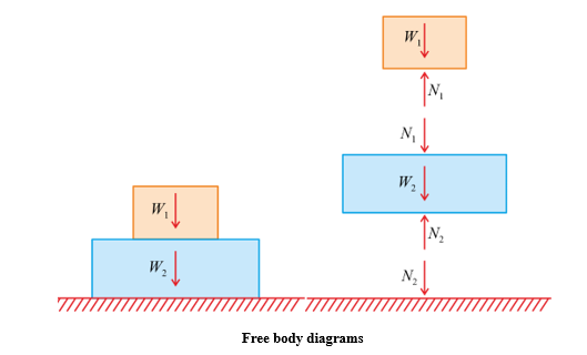
A block resting on a table experiences two forces: the downward gravitational force from Earth and the upward normal force from the table.
▶️ Answer / Explanation
Each force results from a distinct interaction:
- The gravitational force arises from the Earth–block interaction.
- The normal force arises from the contact between the table and the block.
Without these interactions, neither force would exist — all forces originate from other objects or systems.
Example
Two students on skateboards push off each other while at rest on a frictionless surface.
▶️ Answer / Explanation
Each student exerts a force on the other — these are equal in magnitude and opposite in direction. Inside the two-student system, these internal forces cancel, so the net internal force is zero. However, each individual moves because they experience external forces from one another, changing their individual momenta while conserving total system momentum.
Contact Forces and Their Origin
Contact forces describe the interactions between two objects or systems that are physically touching. Although they appear macroscopic, they actually arise from microscopic interatomic electric forces between the atoms of the interacting surfaces.
- Contact forces prevent objects from penetrating one another by balancing repulsive electrical forces at the atomic level.

They include forces such as:
- Normal force (N): Acts perpendicular to the surface, preventing overlap of materials.
- Frictional force (f): Acts parallel to the surface, opposing relative motion.
- Tension force (T): Transmitted through ropes, strings, or cables.
- Applied force (Fₐ): Any external push or pull through physical contact.
- At the atomic scale, these result from electrostatic repulsion and bond deformation between atoms.
Key Idea: Even though contact forces seem mechanical, they are ultimately caused by the electromagnetic interaction between charged particles within matter.
Example
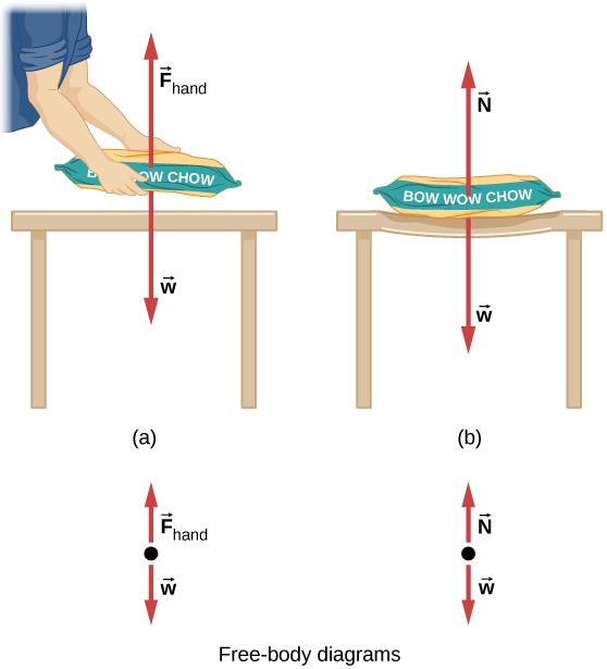
Describe when a book rests on a table without moving. The table exerts an upward normal force on the book that balances its weight.
▶️ Answer / Explanation
Step 1: Identify forces acting on the book:
- Gravitational force \( \mathrm{(F_g = mg)} \) downward from Earth.
- Normal force \( \mathrm{(F_N)} \) upward from the table.
Step 2: Physical origin:
The table’s atoms are compressed slightly by the book’s weight. Electrostatic repulsion between the negatively charged electron clouds in the table’s atoms and the book’s atoms produces an upward restoring force — the normal force.
Step 3: Equilibrium condition:
\( \mathrm{F_N = F_g = mg} \)
Result: The book remains at rest because the net force on it is zero — the upward normal force balances the downward gravitational force, both arising from distinct interactions.
Free-Body Diagrams (FBDs)
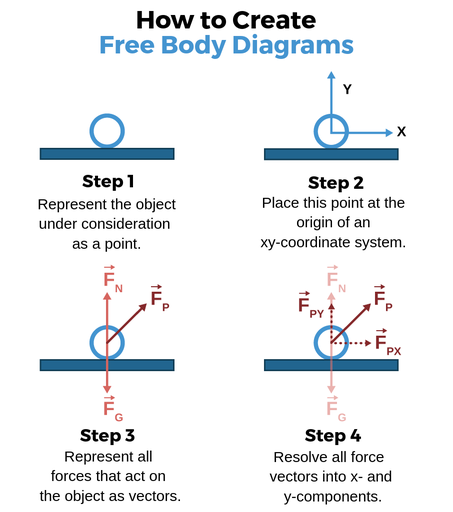
Purpose and Use of Free-Body Diagrams
A free-body diagram (FBD) is a tool used to visually represent all the forces acting on a single object or system. It helps in determining the net force and writing the corresponding Newton’s second law equations for that object.
- Each force vector shows both the magnitude and direction of a force acting on the object.
- Only forces acting on the object are included — not the ones the object exerts on others.
- FBDs are essential for translating physical situations into mathematical form.
Example
A block is pulled across a horizontal surface by a rope with tension \( \mathrm{T} \) at an angle \( \mathrm{\theta} \) above the horizontal. The block experiences friction.
▶️ Answer / Explanation
The FBD includes four forces:
- Weight: \( \mathrm{mg} \) downward.
- Normal force: \( \mathrm{F_N} \) upward.
- Tension: \( \mathrm{T} \) at angle \( \mathrm{\theta} \) above horizontal.
- Friction: \( \mathrm{f_k} \) opposite the direction of motion.
Equilibrium in vertical direction: \( \mathrm{F_N = mg – T\sin\theta} \)
Horizontal acceleration: \( \mathrm{a = \dfrac{T\cos\theta – f_k}{m}} \)
Representation of Environmental Forces
A free-body diagram shows each force exerted by the environment on the object or system. Every arrow corresponds to one distinct physical interaction (contact or field force).
- Forces may include gravity, normal, friction, tension, drag, spring, or electric forces.
- Each vector points in the direction the environment exerts the force on the object.
- For clarity, internal forces within a system are not shown in a single-object FBD.
Example
A hanging mass is attached to a string and in equilibrium.
▶️ Answer / Explanation
The FBD includes two forces acting on the mass:
- Gravitational force \( \mathrm{(F_g = mg)} \) downward, due to Earth.
- Tension \( \mathrm{(T)} \) upward, due to the string.
These are environmental forces acting on the object from external sources — the Earth and the string. At equilibrium: \( \mathrm{T = mg} \).
Representing Forces from the Center of Mass
In a free-body diagram, all forces acting on a system are drawn as vectors originating from its center of mass (COM). This convention treats the system as if all mass were concentrated at the COM.
- For extended bodies, external forces can be represented as acting through the COM for translational motion analysis.
- This simplification allows use of \( \mathrm{\sum \vec{F} = M\vec{a}_{cm}} \).
Key Idea: The FBD focuses on the net external forces on the system; torques or rotations can be considered separately if needed.
Example
A car accelerating on a flat road experiences thrust, drag, normal force, and gravity. In the FBD, all these forces are drawn from the car’s center of mass.
▶️ Answer / Explanation
The four forces are:
- Thrust forward from the engine.
- Drag (air resistance) backward.
- Normal force upward from the road.
- Gravitational force downward from Earth.
Although these forces act at different physical points, in translational motion they are represented as acting through the center of mass for simplicity. Net force determines acceleration: \( \mathrm{F_{thrust} – F_{drag} = Ma_{cm}} \).
Choosing an Appropriate Coordinate System
Choosing a coordinate system aligned with the motion or acceleration of the object simplifies analysis of a free-body diagram. One axis is usually set parallel to the direction of acceleration or to a surface, making the components of forces easier to resolve.
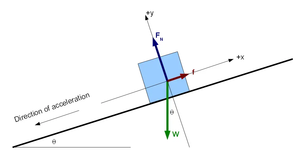
- For motion on an inclined plane, the x-axis is often chosen parallel to the incline.
- This orientation eliminates the need for additional trigonometric transformations for acceleration components.
Key Relationship:
\( \mathrm{\sum F_{\parallel} = m a_{\parallel}} \)
\( \mathrm{\sum F_{\perp} = 0 \text{ (if no motion perpendicular to surface)}} \)
Example
A block of mass \( \mathrm{m} \) rests on an inclined plane at angle \( \mathrm{\theta} \). Find the components of the gravitational force relative to the plane.
▶️ Answer / Explanation
Step 1: Choose axes:
- x-axis parallel to incline (down the slope)
- y-axis perpendicular to incline
Step 2: Resolve gravity into components:
\( \mathrm{F_{g\parallel} = mg\sin\theta} \), \( \mathrm{F_{g\perp} = mg\cos\theta} \)
Step 3: Apply equilibrium condition if at rest:
\( \mathrm{F_N = mg\cos\theta} \)
Result: Choosing the incline-aligned axes makes the motion analysis straightforward — the only unbalanced force is along the plane.