Torque and the Lever Arm
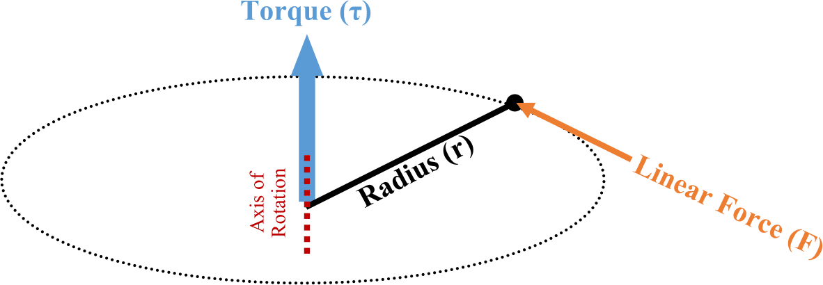
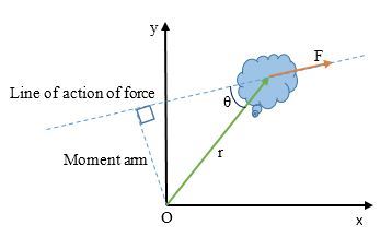
Torque (\( \mathrm{\tau} \)) is the rotational equivalent of force. It measures how effectively a force causes rotation about a fixed axis. The magnitude of the torque depends on the magnitude of the force, the distance from the axis of rotation, and the angle between the force and position vectors.
\( \mathrm{\vec{\tau} = \vec{r} \times \vec{F}} \)
\( \mathrm{|\tau| = rF\sin\theta} \)
- \( \mathrm{\vec{\tau}} \): torque vector (direction given by the right-hand rule)
- \( \mathrm{\vec{r}} \): position vector from the axis of rotation to the point of application of force
- \( \mathrm{\vec{F}} \): applied force
- \( \mathrm{\theta} \): angle between \( \mathrm{\vec{r}} \) and \( \mathrm{\vec{F}} \)
Key Idea: Only the component of force perpendicular to the position vector contributes to torque. The parallel component produces no rotational effect.
\( \mathrm{\tau = rF_{\perp}} \)
- Torque is maximum when the force acts perpendicular to the lever arm (\( \mathrm{\theta = 90°} \)).
- Torque is zero when the force acts along the lever arm (\( \mathrm{\theta = 0°} \)).
The Lever Arm
The lever arm (\( \mathrm{r_{\perp}} \)) is the perpendicular distance from the axis of rotation to the line of action of the force. It represents the shortest distance between the axis and the line along which the force acts.
\( \mathrm{\tau = F r_{\perp}} \)
- \( \mathrm{r_{\perp} = r\sin\theta} \)
- \( \mathrm{r_{\perp}} \): lever arm (in meters)
- \( \mathrm{F} \): force (in newtons)
- \( \mathrm{\tau} \): torque (in newton–meters, \( \mathrm{N·m} \))
Key Idea: The lever arm gives a convenient way to calculate torque geometrically.
Example
A force of \( \mathrm{20\,N} \) is applied to a wrench at a distance of \( \mathrm{0.25\,m} \) from the pivot point. The force acts at an angle of \( \mathrm{60^\circ} \) to the wrench handle. Find the torque produced.
▶️ Answer / Explanation
Step 1: Use the torque formula \( \mathrm{\tau = rF\sin\theta} \):
\( \mathrm{\tau = (0.25)(20)\sin(60°)} \)
Step 2: Simplify the expression:
\( \mathrm{\tau = (5)(0.866) = 4.33\,N·m} \)
Result: The torque produced by the applied force is \( \mathrm{4.33\,N·m} \).
Torque Representation Using Force Diagrams
Force diagrams are visual tools used to represent and analyze the torques acting on a rigid system. They are similar to free-body diagrams but include additional information showing how forces cause rotational effects about a specific axis.
In a torque (or rotational) force diagram:
- Each force vector acting on the object is represented by an arrow showing its magnitude and direction.
- The point of application of each force is shown relative to the axis of rotation.
- The angle between the force and the position vector is indicated, which determines the torque’s magnitude.
- Each torque is labeled as clockwise (−) or counterclockwise (+) according to the chosen sign convention.
Key Idea: Torque diagrams extend free-body diagrams to rotational systems. They help identify how multiple forces combine to produce a net torque, determining whether the system will rotate, stay in equilibrium, or accelerate rotationally.
Representation and Calculation: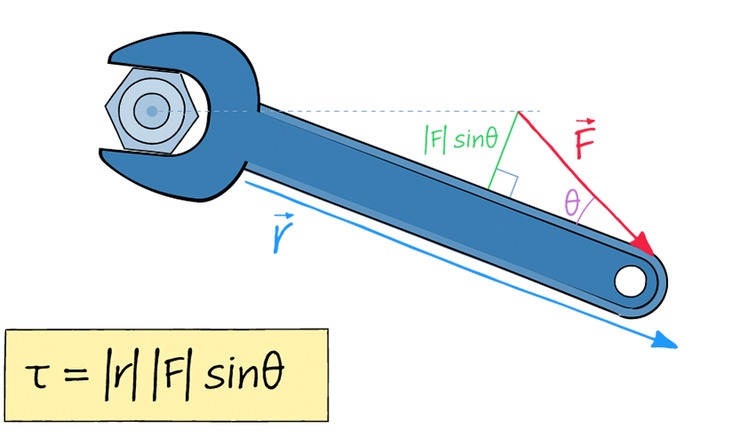
Each torque can be found from the force diagram using the equation:
\( \mathrm{|\tau| = rF\sin\theta} \)
- \( \mathrm{r} \): perpendicular distance (lever arm) from the axis to the force’s line of action
- \( \mathrm{F} \): magnitude of the applied force
- \( \mathrm{\theta} \): angle between \( \mathrm{\vec{r}} \) and \( \mathrm{\vec{F}} \)
Positive torque: counterclockwise rotation
Negative torque: clockwise rotation
Force Diagram vs. Free-Body Diagram
| Feature | Free-Body Diagram | Force Diagram (for Torque) |
|---|---|---|
| Purpose | Analyze translational motion (forces and acceleration) | Analyze rotational motion (torques and angular acceleration) |
| Force Location | Forces act through the object’s center of mass | Forces are shown at points of application relative to the rotation axis |
| Additional Feature | No lever arms shown | Shows lever arms and torque direction (CW or CCW) |
Example
A uniform beam of length \( \mathrm{2.0\,m} \) is pivoted at one end and held horizontally by an upward force of \( \mathrm{40\,N} \) applied at the other end. The beam’s weight (\( \mathrm{30\,N} \)) acts at its center. Draw a force diagram and find the net torque about the pivot.
▶️ Answer / Explanation
Step 1: Draw the force diagram.
- The pivot (axis of rotation) is at one end.
- A downward force of \( \mathrm{30\,N} \) acts at \( \mathrm{1.0\,m} \) from the pivot (center of the beam).
- An upward force of \( \mathrm{40\,N} \) acts at \( \mathrm{2.0\,m} \) from the pivot.
Step 2: Calculate torques using \( \mathrm{\tau = rF} \) (forces are perpendicular to beam).
Torque from beam’s weight: \( \mathrm{\tau_1 = (1.0)(30) = 30\,N·m} \) (clockwise, negative)
Torque from support force: \( \mathrm{\tau_2 = (2.0)(40) = 80\,N·m} \) (counterclockwise, positive)
Step 3: Find net torque:
\( \mathrm{\tau_{net} = +80 – 30 = +50\,N·m} \)
Result: The net torque about the pivot is \( \mathrm{50\,N·m} \) counterclockwise. The positive result indicates the beam tends to rotate upward on the right side.
Vector Definition of Torque
The torque exerted on a rigid system about a chosen pivot point by an applied force is a vector quantity. It is defined as the cross-product of the position vector \( \mathrm{\vec{r}} \) (from the pivot to the point of force application) and the force vector \( \mathrm{\vec{F}} \): 
\( \mathrm{\vec{\tau} = \vec{r} \times \vec{F}} \)
- \( \mathrm{\vec{\tau}} \): torque vector
- \( \mathrm{\vec{r}} \): position vector (from the axis of rotation to the point where the force is applied)
- \( \mathrm{\vec{F}} \): applied force vector
Magnitude of Torque:
The magnitude of the torque vector is given by the product of the magnitudes of \( \mathrm{\vec{r}} \) and \( \mathrm{\vec{F}} \), and the sine of the angle \( \mathrm{\theta} \) between them:
\( \mathrm{|\vec{\tau}| = rF\sin\theta} \)
- \( \mathrm{r} \): distance from the pivot (meters)
- \( \mathrm{F} \): applied force (newtons)
- \( \mathrm{\theta} \): angle between \( \mathrm{\vec{r}} \) and \( \mathrm{\vec{F}} \)
Cross-Product and Direction of Torque
The cross-product between two vectors \( \mathrm{\vec{A}} \) and \( \mathrm{\vec{B}} \) produces a third vector \( \mathrm{\vec{A} \times \vec{B}} \), whose magnitude and direction are defined as:
\( \mathrm{|\vec{A} \times \vec{B}| = AB\sin\theta} \)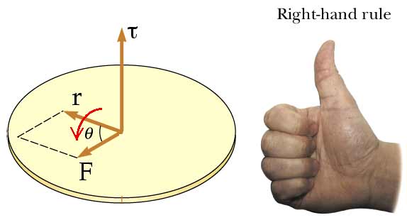
\( \mathrm{\text{Direction: perpendicular to both } \vec{A} \text{ and } \vec{B}} \)
The resulting vector is normal to the plane defined by \( \mathrm{\vec{A}} \) and \( \mathrm{\vec{B}} \).
Right-Hand Rule for Torque Direction:
The direction of the torque vector can be found using the right-hand rule:
- Point the fingers of your right hand along the direction of \( \mathrm{\vec{r}} \).
- Rotate them toward \( \mathrm{\vec{F}} \) through the smaller angle \( \mathrm{\theta} \).
- Your thumb then points in the direction of the torque vector \( \mathrm{\vec{\tau}} \).
Interpretation:
- If the torque vector points out of the page, the rotation is counterclockwise (positive torque).
- If the torque vector points into the page, the rotation is clockwise (negative torque).
Example
A force of \( \mathrm{10\,N} \) acts at the end of a \( \mathrm{0.40\,m} \) wrench handle at an angle of \( \mathrm{90^\circ} \) to the handle. Determine the magnitude and direction of the torque about the pivot.
▶️ Answer / Explanation
Step 1: Use the vector torque equation:
\( \mathrm{|\vec{\tau}| = rF\sin\theta} \)
Step 2: Substitute values:
\( \mathrm{|\vec{\tau}| = (0.40)(10)\sin(90^\circ) = 4.0\,N·m} \)
Step 3: Determine the direction using the right-hand rule:
Fingers point along \( \mathrm{\vec{r}} \), curl toward \( \mathrm{\vec{F}} \); thumb points out of the page.
Result: Torque magnitude = \( \mathrm{4.0\,N·m} \), direction = out of the page (counterclockwise rotation).