Angular Momentum of a Rigid System and a Particle
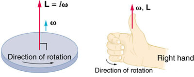
The angular momentum of a rigid system about a specific axis is the product of its rotational inertia and its angular velocity.
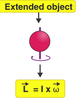
\( \mathrm{L = I\omega} \)
- \( \mathrm{L} \): angular momentum (in \( \mathrm{kg·m^2/s} \))
- \( \mathrm{I} \): moment of inertia of the rigid system (in \( \mathrm{kg·m^2} \))
- \( \mathrm{\omega} \): angular velocity about the chosen axis (in \( \mathrm{rad/s} \))
Key Idea: A system with a large moment of inertia or high angular velocity will have a large angular momentum. Angular momentum is a vector quantity whose direction is determined by the right-hand rule (along the axis of rotation).
Example
A solid disk of mass \( \mathrm{5.0\,kg} \) and radius \( \mathrm{0.20\,m} \) rotates at \( \mathrm{10\,rad/s} \). Find the magnitude of its angular momentum about its central axis.
▶️ Answer / Explanation
Step 1: For a solid disk, \( \mathrm{I = \tfrac{1}{2}MR^2} \).
\( \mathrm{I = \tfrac{1}{2}(5.0)(0.20)^2 = 0.10\,kg·m^2} \)
Step 2: Apply \( \mathrm{L = I\omega} \):
\( \mathrm{L = (0.10)(10) = 1.0\,kg·m^2/s} \)
Result: The disk’s angular momentum about its central axis is \( \mathrm{1.0\,kg·m^2/s} \), directed along the axis by the right-hand rule.
Angular Momentum of a Particle
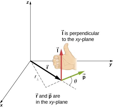
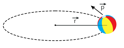
The angular momentum of a moving particle (or object) about a point is defined as the cross product of the particle’s position vector and its linear momentum vector:
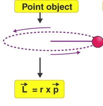
\( \mathrm{\vec{L} = \vec{r} \times \vec{p}} \)
- \( \mathrm{\vec{L}} \): angular momentum vector (in \( \mathrm{kg·m^2/s} \))
- \( \mathrm{\vec{r}} \): position vector from the reference point to the particle (in \( \mathrm{m} \))
- \( \mathrm{\vec{p}} \): linear momentum of the particle (\( \mathrm{p = mv} \))
The magnitude of angular momentum is given by:
\( \mathrm{L = r p \sin\theta = (mvr)\sin\theta} \)
Key Idea: The angle \( \mathrm{\theta} \) between \( \mathrm{\vec{r}} \) and \( \mathrm{\vec{p}} \) determines how much of the particle’s motion contributes to rotation about the chosen point.
Example
A \( \mathrm{0.20\,kg} \) ball moves in a straight line at \( \mathrm{8.0\,m/s} \). At a given instant, it is \( \mathrm{0.50\,m} \) away from a point O, and its velocity makes an angle of \( \mathrm{30^\circ} \) with the line joining the ball and point O. Find the magnitude of the ball’s angular momentum about O.
▶️ Answer / Explanation
Step 1: Use the formula \( \mathrm{L = mvr\sin\theta} \).
\( \mathrm{L = (0.20)(8.0)(0.50)\sin(30^\circ)} \)
Step 2: Simplify:
\( \mathrm{L = (0.20)(8.0)(0.50)(0.5) = 0.40\,kg·m^2/s} \)
Result: The angular momentum of the ball about point O is \( \mathrm{0.40\,kg·m^2/s} \).
Choice of Axis for Angular Momentum
The choice of the reference axis or point about which angular momentum is calculated affects its value. The same object can have different angular momenta depending on where the axis is chosen.
- If the axis passes through the object’s center of mass, the calculation uses \( \mathrm{I_{cm}\omega} \).
- If the axis is external, the position vector \( \mathrm{\vec{r}} \) must be measured from that new point.
Key Idea: Angular momentum depends not only on the object’s rotation but also on how it is positioned and moves relative to the chosen point or axis.
Example
A \( \mathrm{0.5\,kg} \) particle moves at \( \mathrm{4.0\,m/s} \) along a straight line \( \mathrm{0.30\,m} \) from the origin. Compare the angular momentum about (a) the origin and (b) a point on the line of motion.
▶️ Answer / Explanation
Case (a): About the origin, \( \mathrm{r = 0.30\,m} \), and velocity is perpendicular.
\( \mathrm{L = mvr = (0.5)(4.0)(0.30) = 0.60\,kg·m^2/s} \)
Case (b): About a point on the line of motion, \( \mathrm{\theta = 0^\circ} \) → \( \mathrm{\sin\theta = 0} \).
\( \mathrm{L = 0} \)
Result: Angular momentum depends on the chosen axis. It’s maximum when the motion is perpendicular to the position vector, and zero when it’s parallel.
Factors Affecting the Angular Momentum of a Moving Object
The angular momentum of an object moving in a straight line depends on:
- The perpendicular distance (\( \mathrm{r_\perp} \)) from the reference point to the line of motion.
- The object’s mass \( \mathrm{m} \).
- Its linear speed \( \mathrm{v} \).
- The angle \( \mathrm{\theta} \) between the radial line and velocity vector.
Mathematically,
\( \mathrm{L = mvr\sin\theta} \)
Key Idea: Only the component of velocity perpendicular to the radial direction contributes to angular momentum. If the velocity points directly toward or away from the reference point, \( \mathrm{\sin\theta = 0} \), and \( \mathrm{L = 0} \).
Example
A \( \mathrm{0.3\,kg} \) puck slides across frictionless ice at \( \mathrm{5.0\,m/s} \). At a certain instant, its distance from a reference point O is \( \mathrm{0.40\,m} \), and the velocity makes an angle of \( \mathrm{45^\circ} \) with the line joining it to O. Calculate its angular momentum about O.
▶️ Answer / Explanation
Step 1: Use \( \mathrm{L = mvr\sin\theta} \):
\( \mathrm{L = (0.3)(5.0)(0.40)\sin(45^\circ)} \)
Step 2: Simplify:
\( \mathrm{L = (0.3)(5.0)(0.40)(0.707) = 0.424\,kg·m^2/s} \)
Result: The puck’s angular momentum about O is \( \mathrm{0.42\,kg·m^2/s} \).
Angular Impulse
Angular impulse is defined as the product of the torque exerted on an object or rigid system and the time interval during which that torque acts. It represents the change in the system’s angular momentum.
\( \mathrm{J_\tau = \int \tau\,dt} \)
- \( \mathrm{J_\tau} \): angular impulse (in \( \mathrm{N·m·s} \))
- \( \mathrm{\tau} \): torque acting on the system (in \( \mathrm{N·m} \))
- \( \mathrm{t} \): time interval (in seconds)
The angular impulse–angular momentum theorem states that:
\( \mathrm{J_\tau = \Delta L = L_f – L_i = I(\omega_f – \omega_i)} \)
This shows that the angular impulse applied to a system equals the change in its angular momentum.
Direction of Angular Impulse
Angular impulse is a vector quantity with the same direction as the torque that produces it. The direction is given by the right-hand rule — if the torque tends to rotate the object counterclockwise, the angular impulse vector points outward along the rotation axis.
Example
A constant torque of \( \mathrm{2.5\,N·m} \) acts on a rotating flywheel for \( \mathrm{4.0\,s} \). Find the angular impulse delivered to the flywheel and its change in angular momentum.
▶️ Answer / Explanation
Step 1: For constant torque, angular impulse is:
\( \mathrm{J_\tau = \tau \Delta t} \)
Step 2: Substitute values:
\( \mathrm{J_\tau = (2.5)(4.0) = 10.0\,N·m·s} \)
Step 3: Using \( \mathrm{J_\tau = \Delta L} \):
The flywheel’s angular momentum increases by \( \mathrm{10.0\,N·m·s} \) in the direction of the applied torque.
Result: \( \mathrm{J_\tau = \Delta L = 10.0\,N·m·s} \), directed along the torque vector.
Angular Impulse from a Torque–Time Graph
The angular impulse delivered to an object can also be determined graphically. It is equal to the area under the torque vs. time curve:
\( \mathrm{J_\tau = \text{Area under the } \tau\text{–}t \text{ curve}} \)
- Positive torque → increases angular momentum.
- Negative torque → decreases angular momentum.
- The total area (taking sign into account) gives the net angular impulse.
Example
The torque acting on a rotating disk increases linearly from \( \mathrm{0} \) to \( \mathrm{4.0\,N·m} \) during the first \( \mathrm{2.0\,s} \), and then remains constant for another \( \mathrm{2.0\,s} \). Determine the total angular impulse imparted to the disk.
▶️ Answer / Explanation
Step 1: The angular impulse equals the total area under the \( \mathrm{\tau\text{–}t} \) graph.
The graph consists of:
- A triangle from \( \mathrm{0} \) to \( \mathrm{2.0\,s} \)
- A rectangle from \( \mathrm{2.0\,s} \) to \( \mathrm{4.0\,s} \)
Step 2: Calculate each area:
Triangle: \( \mathrm{A_1 = \tfrac{1}{2}(2.0)(4.0) = 4.0\,N·m·s} \)
Rectangle: \( \mathrm{A_2 = (2.0)(4.0) = 8.0\,N·m·s} \)
Step 3: Add them to find total impulse:
\( \mathrm{J_\tau = A_1 + A_2 = 4.0 + 8.0 = 12.0\,N·m·s} \)
Result: The disk receives an angular impulse of \( \mathrm{12.0\,N·m·s} \), causing an equal increase in its angular momentum.
Angular Impulse and Change in Angular Momentum
The change in angular momentum of an object or rigid system can be described by comparing the magnitudes of the final and initial angular momenta:
\( \mathrm{\Delta L = L_f – L_i} \)
- \( \mathrm{L_i} \): initial angular momentum
- \( \mathrm{L_f} \): final angular momentum
- \( \mathrm{\Delta L} \): change in angular momentum
Key Idea: A change in angular momentum occurs only if a net external torque acts on the system. If no external torque acts (\( \mathrm{\sum \tau = 0} \)), then \( \mathrm{\Delta L = 0} \), and the system’s angular momentum is conserved.
Example
A disk initially rotating at \( \mathrm{5.0\,rad/s} \) slows to \( \mathrm{2.0\,rad/s} \) due to friction. The moment of inertia of the disk is \( \mathrm{0.40\,kg·m^2} \). Find the change in its angular momentum.
▶️ Answer / Explanation
Step 1: Compute initial and final angular momenta:
\( \mathrm{L_i = I\omega_i = (0.40)(5.0) = 2.0\,kg·m^2/s} \)
\( \mathrm{L_f = I\omega_f = (0.40)(2.0) = 0.8\,kg·m^2/s} \)
Step 2: Find change in angular momentum:
\( \mathrm{\Delta L = L_f – L_i = 0.8 – 2.0 = -1.2\,kg·m^2/s} \)
Result: The negative sign indicates that the disk’s angular momentum decreased by \( \mathrm{1.2\,kg·m^2/s} \) due to the opposing torque from friction.
Rotational Impulse–Momentum Theorem
The rotational impulse–momentum theorem states that the angular impulse applied to a rigid system equals its change in angular momentum:
\( \mathrm{\Delta L = \int_{t_1}^{t_2} \tau\,dt} \)
Key Idea: This is the rotational analog of the linear impulse–momentum theorem \( \mathrm{F\,\Delta t = \Delta p} \). If torque varies with time, the total impulse is obtained by integrating over the time interval.
Example
A constant torque of \( \mathrm{3.0\,N·m} \) acts on a disk for \( \mathrm{2.0\,s} \). The disk’s rotational inertia is \( \mathrm{0.50\,kg·m^2} \). Find the change in angular velocity and angular momentum.
▶️ Answer / Explanation
Step 1: Apply impulse–momentum relation:
\( \mathrm{\Delta L = \tau \Delta t = (3.0)(2.0) = 6.0\,N·m·s} \)
Step 2: Use \( \mathrm{\Delta L = I\,\Delta\omega} \) to find \( \mathrm{\Delta\omega} \):
\( \mathrm{\Delta\omega = \dfrac{\Delta L}{I} = \dfrac{6.0}{0.50} = 12\,rad/s} \)
Result: The disk’s angular velocity increases by \( \mathrm{12\,rad/s} \) and its angular momentum increases by \( \mathrm{6.0\,N·m·s} \).
Angular Impulse Equals Change in Angular Momentum
The angular impulse applied to an object or rigid system equals its change in angular momentum:
\( \mathrm{J_\tau = \Delta L = \int_{t_1}^{t_2} \tau\,dt} \)
Key Idea: The greater the torque or the longer it acts, the greater the change in angular momentum.
Relation to Newton’s Second Law for Rotation
The rotational impulse–momentum theorem is a direct result of Newton’s Second Law for Rotation when the moment of inertia is constant:
\( \mathrm{\tau_{net} = \dfrac{dL}{dt} = I\dfrac{d\omega}{dt} = I\alpha} \)
Derivation:
\( \mathrm{\int_{t_1}^{t_2} \tau_{net}\,dt = \int_{t_1}^{t_2} dL \Rightarrow \Delta L = \int_{t_1}^{t_2} \tau_{net}\,dt} \)
Hence, the impulse–momentum relationship naturally follows from the fundamental law of rotational dynamics.
Torque and the Slope of the Angular Momentum–Time Graph
The net torque exerted on a system is equal to the rate of change of its angular momentum, or equivalently, the slope of its angular momentum–time graph:
\( \mathrm{\tau_{net} = \dfrac{dL}{dt}} \)
Key Idea: – A steeper slope → greater torque. – A flat \( \mathrm{L\text{–}t} \) graph indicates \( \mathrm{\tau_{net} = 0} \), i.e., angular momentum is conserved.
Example
The angular momentum of a rotating wheel changes linearly from \( \mathrm{2.0\,kg·m^2/s} \) to \( \mathrm{8.0\,kg·m^2/s} \) in \( \mathrm{3.0\,s} \). Find the net torque on the wheel.
▶️ Answer / Explanation
Step 1: From the slope of \( \mathrm{L–t} \):
\( \mathrm{\tau_{net} = \dfrac{\Delta L}{\Delta t} = \dfrac{8.0 – 2.0}{3.0} = 2.0\,N·m} \)
Result: The wheel experiences a constant net torque of \( \mathrm{2.0\,N·m} \).
Angular Impulse from the Torque–Time Graph
The angular impulse delivered to a system equals the area under the net torque vs. time graph:
\( \mathrm{J_\tau = \int \tau_{net}\,dt = \text{Area under the } \tau\text{–}t \text{ curve}} \)
- Positive area → angular momentum increases.
- Negative area → angular momentum decreases.
Example
The torque on a rigid body increases linearly from \( \mathrm{0} \) to \( \mathrm{3.0\,N·m} \) during the first \( \mathrm{2.0\,s} \), then decreases linearly back to zero at \( \mathrm{t = 4.0\,s} \). Find the total change in angular momentum.
▶️ Answer / Explanation
Step 1: The torque–time graph forms a triangle with base \( \mathrm{4.0\,s} \) and height \( \mathrm{3.0\,N·m} \).
Area (impulse) \( \mathrm{J_\tau = \tfrac{1}{2}(4.0)(3.0) = 6.0\,N·m·s} \)
Step 2: By the impulse–momentum theorem, \( \mathrm{J_\tau = \Delta L} \).
\( \mathrm{\Delta L = 6.0\,N·m·s} \)
Result: The object’s angular momentum increases by \( \mathrm{6.0\,N·m·s} \).