
AP Physics C Mechanics - 7.4 Energy of Simple Harmonic Oscillators- Exam Style questions- FRQs
Energy of Simple Harmonic Oscillators AP Physics C Mechanics FRQ
Unit 7: Oscillations
Weightage : 20-15%
Question
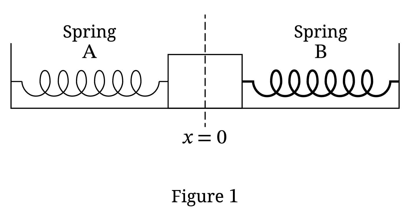
In Scenario 1, a system composed of two springs, $A$ and $B$, and a block of mass $m$ is at rest on a horizontal surface. Friction between the block and the surface is negligible. Each spring is attached to a fixed wall and the block, as shown in Figure 1. Spring $A$ has a spring constant $k$ and Spring $B$ has a spring constant $2k$. Each spring is at its relaxed length when the block is at position $x=0$ as shown.
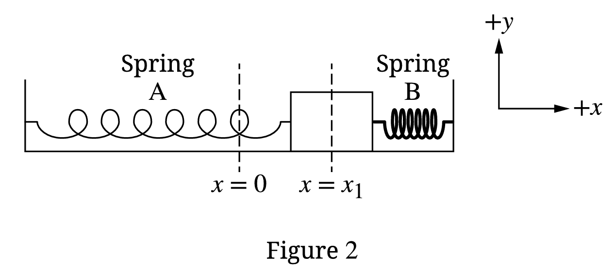
The block is moved to $x=x_{1}$ and held at rest, as shown in Figure 2.
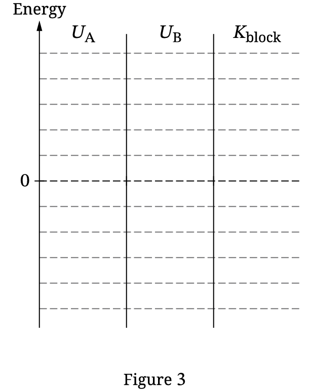
A. An energy bar chart can be used to represent the elastic potential energy $U_{A}$ of Spring A, the elastic potential energy $U_{B}$ of Spring B, and the kinetic energy $K_{\text{block}}$ of the block. On the energy bar chart in Figure 3, draw shaded bars to represent the energy of the system for when the block is at $x=x_{1}$.
- The height of the shaded bars should be proportional to the relative values of $U_{A}$, $U_{B}$, and $K_{\text{block}}$.
- Any energy that is equal to zero should be represented by a distinct line on the zero-energy line.
B. The block is released from rest at $x=x_{1}$ and begins to oscillate. Derive an expression for the speed $v$ of the block as the block passes through $x=\frac{1}{2}x_{1}$. Express your answer in terms of $m$, $k$, $x_{1}$, and physical constants, as appropriate. Begin your derivation by writing a fundamental physics principle or an equation from the reference information.
C. In Scenario 1, the block oscillates with period $T$. The position $x$ of the block in Scenario 1 as a function of time $t$ is shown in Figure 4.
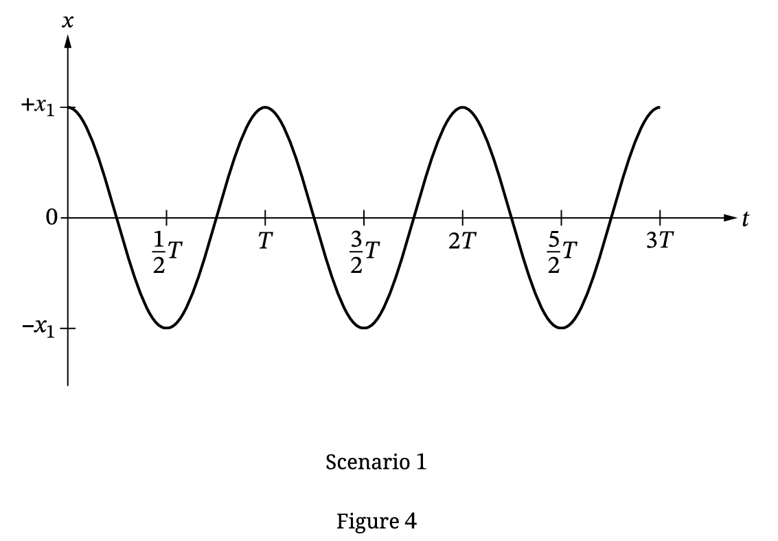
In Scenario 2, the block-springs system is placed on a new surface. There is friction between the block and the new surface. The block is again moved to the same position $x=x_{1}$ and released from rest. The block completes multiple oscillations with the same period as in Scenario 1 before coming to rest. On the axes shown in Figure 5, sketch a graph of the kinetic energy $K$ of the block as a function of $t$ for Scenario 2.
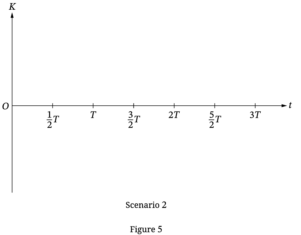
D. In Scenario 3, the block is replaced with a new block of larger mass. The coefficient of kinetic friction between the new block and the surface in Scenario 3 is the same as the coefficient of kinetic friction between the original block and the surface in Scenario 2. The new block is moved to position $x=x_{1}$ and released from rest. The kinetic energy of the new block is plotted as a function of time. Describe how one feature of the graph of $K$ as a function of $t$ in Scenario 3 would differ from the graph you drew in Figure 5 for Scenario 2. Briefly justify your answer.
Most-appropriate topic codes (AP Physics C: Mechanics):
• Topic 7.1 — Defining Simple Harmonic Motion (SHM) (Parts \( \mathrm{C} \), \( \mathrm{D} \))
• Topic 7.2 — Frequency and Period of SHM (Parts \( \mathrm{C} \), \( \mathrm{D} \))
• Topic 7.4 — Energy of Simple Harmonic Oscillators (Parts \( \mathrm{A} \), \( \mathrm{B} \), \( \mathrm{C} \))
• Topic 7.2 — Frequency and Period of SHM (Parts \( \mathrm{C} \), \( \mathrm{D} \))
• Topic 7.4 — Energy of Simple Harmonic Oscillators (Parts \( \mathrm{A} \), \( \mathrm{B} \), \( \mathrm{C} \))
▶️ Answer/Explanation
A.
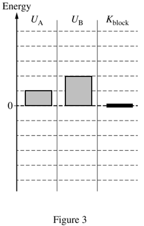
When the block is held at rest at $x = x_1$, its velocity is zero, so the kinetic energy is zero:
$K_{\text{block}} = 0$
Both springs experience the same displacement magnitude $x_1$ from equilibrium. The potential energy stored in a spring is given by $U = \frac{1}{2}kx^2$. Therefore, the ratio of the potential energies matches the ratio of their spring constants:
$U_A = \frac{1}{2}kx_1^2$
$U_B = \frac{1}{2}(2k)x_1^2 = kx_1^2$
$U_B = 2U_A$
To represent this on the chart, draw a bar for $U_A$ with a positive height (e.g., 2 grid units), a bar for $U_B$ with exactly twice that height (e.g., 4 grid units), and a clear horizontal line on the zero mark for $K_{\text{block}}$.
B.
We apply the law of conservation of mechanical energy since friction is negligible in Scenario 1:
$E_i = E_f$
$U_A(x_1) + U_B(x_1) + K_{\text{block}}(x_1) = U_A\left(\frac{1}{2}x_1\right) + U_B\left(\frac{1}{2}x_1\right) + K_{\text{block}}\left(\frac{1}{2}x_1\right)$
$\frac{1}{2}kx_1^2 + \frac{1}{2}(2k)x_1^2 + 0 = \frac{1}{2}k\left(\frac{x_1}{2}\right)^2 + \frac{1}{2}(2k)\left(\frac{x_1}{2}\right)^2 + \frac{1}{2}mv^2$
$\frac{3}{2}kx_1^2 = \frac{1}{8}kx_1^2 + \frac{2}{8}kx_1^2 + \frac{1}{2}mv^2$
$\frac{3}{2}kx_1^2 = \frac{3}{8}kx_1^2 + \frac{1}{2}mv^2$
$\frac{1}{2}mv^2 = \frac{12}{8}kx_1^2 – \frac{3}{8}kx_1^2$
$\frac{1}{2}mv^2 = \frac{9}{8}kx_1^2$
$mv^2 = \frac{9}{4}kx_1^2$
$v^2 = \frac{9kx_1^2}{4m}$
$v = \frac{3}{2}x_{1}\sqrt{\frac{k}{m}}$
C.
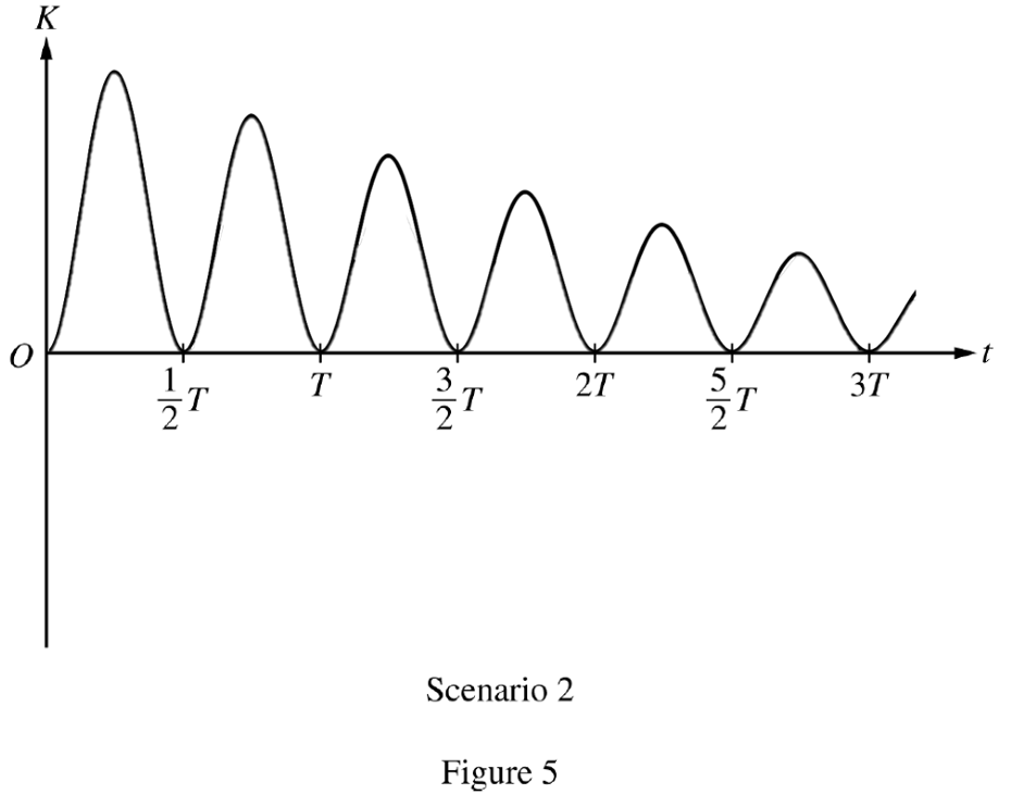
In Scenario 2, friction dampens the system’s mechanical energy over time. The sketched curve for kinetic energy $K(t)$ must follow these properties:
• It must start at zero ($K=0$ at $t=0$) and never go below the time axis because kinetic energy is non-negative ($K \ge 0$).
• The block passes through the equilibrium position $x=0$ at $t = \frac{1}{4}T, \frac{3}{4}T, \frac{5}{4}T$, etc., where kinetic energy reaches a local maximum.
• The block momentarily stops at its turning points where $x = \pm x_{\text{max}}$ at $t = 0, \frac{1}{2}T, T, \frac{3}{2}T, 2T, \frac{5}{2}T, 3T$, meaning the curve must touch zero exactly at every half-period mark.
• Due to non-conservative work done by friction, the total mechanical energy decreases continuously, so the successive peak values of $K(t)$ must become progressivly lower in amplitude.
D.
Feature: The period of the kinetic energy cycles increases (the graph stretches horizontally), and the peaks drop to zero much quicker.
Justification: The period of a mass-spring system is determined by the formula $T_s = 2\pi\sqrt{\frac{m}{k_{\text{eff}}}}$. Increasing the mass directly lengthens the period of oscillation, which spaces out the time intervals between the points where kinetic energy hits zero. Additionally, a greater mass scales up the normal force $F_N = mg$ and consequently enhances the kinetic friction force $F_k = \mu mg$. This larger damping force removes mechanical energy from the system at a faster rate, dragging the peak kinetic energy values down more aggressively than seen in Scenario 2.