▶️ Answer/Explanation
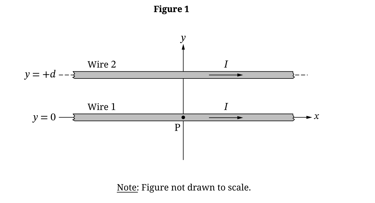
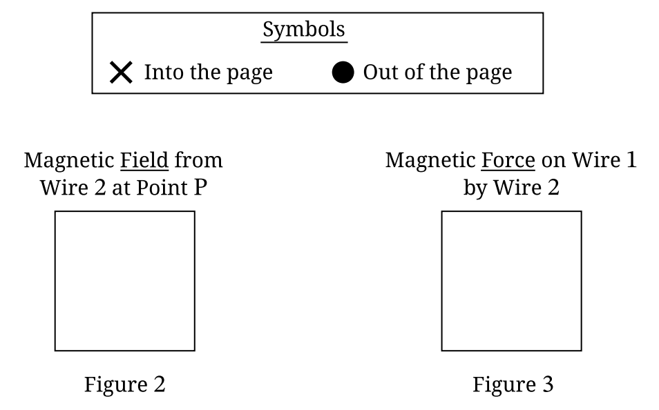
(a)(i)
• Magnetic Field: Into the page (\(\otimes\)). Right Hand Rule: Thumb in \(+x\) (current), fingers curl into page below wire.
• Magnetic Force: Up (\(+y\)). Parallel currents attract; Wire 2 pulls Wire 1 upward.
(a)(ii)
Forces on Wire 1 must balance: \(\vec{F}_{2 \to 1} + \vec{F}_{3 \to 1} = 0\).
Wire 2 exerts an upward attractive force. Wire 3 must exert a downward attractive force.
For attraction, currents must be parallel (same direction), so Wire 3 must be located below Wire 1 (\(y_3 < 0\)).
Equating magnitudes:
\(\frac{\mu_0 I_1 I_2 L}{2\pi d} = \frac{\mu_0 I_1 I_3 L}{2\pi |y_3|}\)
\(\frac{I^2}{d} = \frac{I(2I)}{|y_3|} \Rightarrow \frac{1}{d} = \frac{2}{|y_3|}\)
\(|y_3| = 2d \Rightarrow\) \(y_3 = -2d\).
(b)
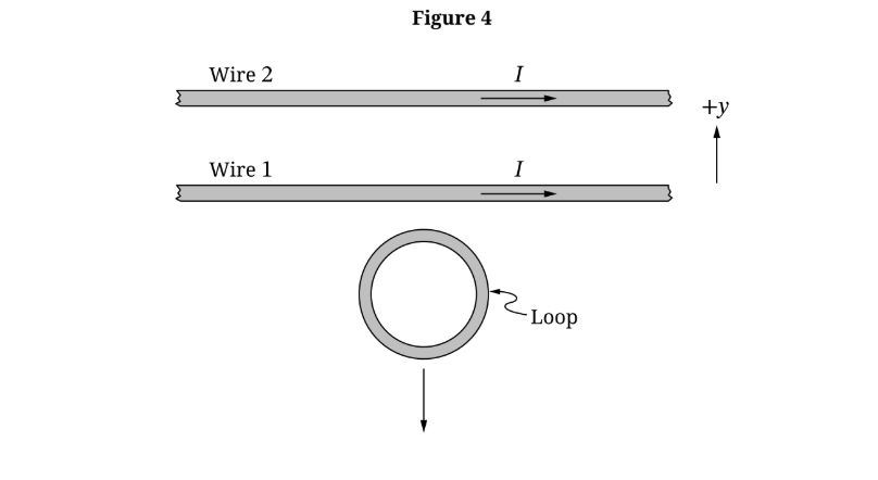
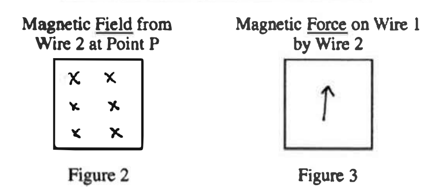
Clockwise.
The magnetic field from Wire 1 below the wire points into the page.
As the loop moves away (\(-y\)), the field strength and flux decrease.
Lenz’s Law: Induced field points into the page to oppose the decrease.
Right Hand Rule: Current must be clockwise.
▶️ Answer/Explanation
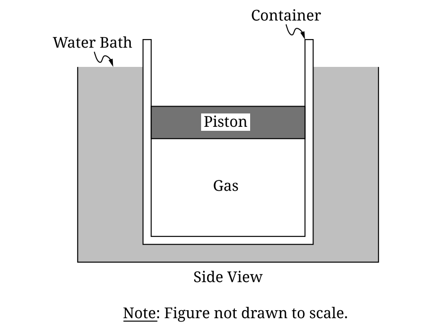
(a)
Forces acting on the piston:
• Upward: \(F_{gas}\) (Force from gas pressure)
• Downward: \(F_{g}\) or \(Mg\) (Weight of the piston) and \(F_{atm}\) (Atmospheric force)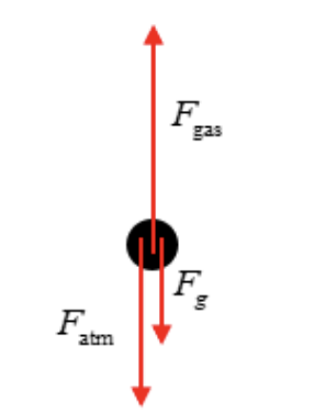
(b)
Internal energy for a monatomic ideal gas: \(U = \frac{3}{2}nRT = \frac{3}{2}PV_0\)
From force equilibrium in part (a): \(P_{gas}A = P_{atm}A + Mg \Rightarrow P = P_{atm} + \frac{Mg}{A}\)
Substitute \(P\):
\(U = \frac{3}{2}V_{0}\left(P_{atm} + \frac{Mg}{A}\right)\)
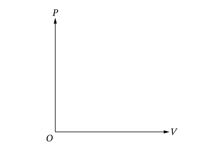
(c)
The process is an isothermal compression (temperature held constant by water bath).
• Curve is concave up.
• Direction is up and to the left (Volume decreases, Pressure increases).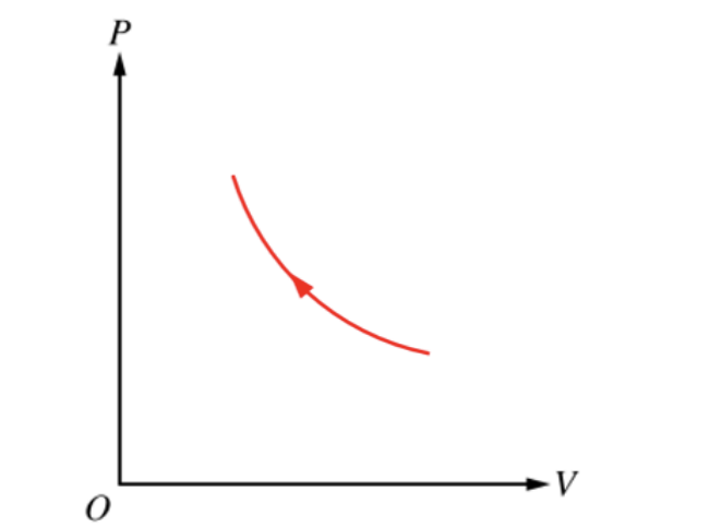
(d)
\(T_{new} > T_{0}\)
Justification: The total mass on the piston has increased, so the gas pressure required for equilibrium is higher (\(P_{new} > P_{initial}\)). Since the volume is restored to \(V_0\) (constant) and \(PV = nRT\), a higher pressure \(P\) requires a higher temperature \(T\).

▶️ Answer/Explanation
(a)
Procedure:
1. Use the ruler to measure the side length \(s\) of the capacitor plates and the plate separation \(d\). Repeat measurements to find an average.
2. Construct a circuit with the battery, switch, resistor, and ammeter (capacitor not needed for \(R\)).
3. Close the switch and measure the current \(I\).
(b)
Analysis:
1. Calculate capacitance \(C = \frac{\epsilon_0 s^2}{d}\).
2. Calculate resistance \(R = \frac{\mathcal{E}}{I}\) using the battery emf \(\mathcal{E}\).
3. Calculate time constant \(\tau = RC\).
(c)(i)
Vertical axis: Charge \(q\) (or \(|\Delta V|\))
Horizontal axis: Potential Difference \(|\Delta V|\) (or \(q\))
(c)(ii) & (iii)
The graph of \(q\) versus \(|\Delta V|\) with the best-fit line:
0246810|ΔV| (V)02468q (x10^-10 C)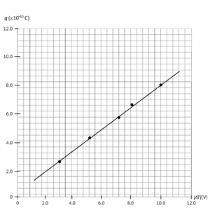
(c)(iv)
\(C\) is the slope of the line \(q = C|\Delta V|\).
Using points on the line \((0,0)\) and \((10.0, 8.0)\):
Slope \(= \frac{8.0 – 0}{10.0 – 0} \times 10^{-10} = 0.8 \times 10^{-10}\)
\(C = 8.0 \times 10^{-11} \text{F}\).
▶️ Answer/Explanation
(a)
Correct.
Violet light has a shorter wavelength \(\lambda\) than red light. Constructive interference occurs when the path length difference \(\Delta \ell = m\lambda\). A shorter \(\lambda\) requires a shorter path difference \(\Delta \ell\) for the same order \(m\). A shorter \(\Delta \ell\) corresponds to a smaller distance from the central bright band.
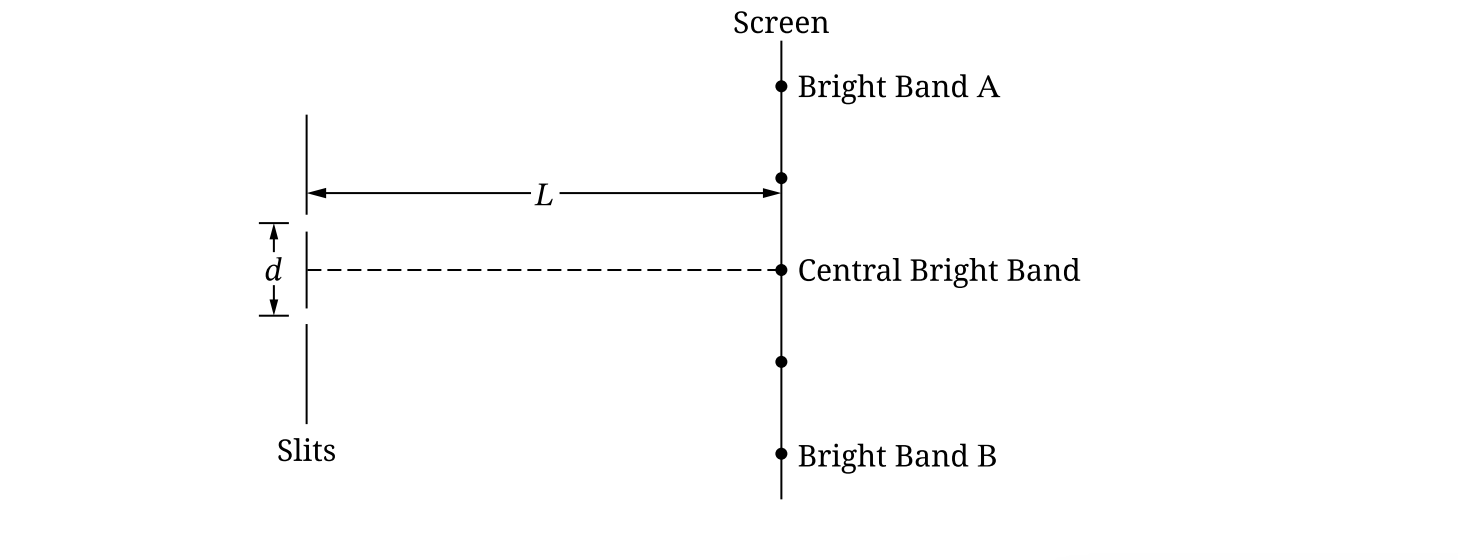
(b)
\(d \sin \theta = m \lambda\)
Using small angle approximation \(\sin \theta \approx \frac{y}{L}\):
\(d \frac{y}{L} = m \lambda \Rightarrow y = \frac{m \lambda L}{d}\)
Band A is the second bright fringe (\(m=2\)) and Band B is the symmetric fringe (\(m=-2\)).
Distance \(= y_A – y_B = \frac{2 \lambda L}{d} – \frac{-2 \lambda L}{d} = \frac{4 \lambda L}{d}\)
Substitute \(\lambda = \frac{c}{f}\):
Distance \(= \frac{4cL}{fd}\)
(c)
Consistent.
The derived expression \(\frac{4cL}{fd}\) shows the distance is inversely proportional to frequency \(f\). Violet light has a higher frequency than red light, resulting in a smaller distance.